Inductive load mix
Motors, transformers and other inductive equipment draw reactive power differently across loaded, lightly loaded and starting conditions.

Engineering problem / poor-power-factor
Poor power factor is a measured system condition, not a product diagnosis; the load profile, reactive demand, harmonics and switching behaviour need to be understood before selecting correction equipment.
Observed signals
Record time, location and operating state before assigning a product or corrective action.
Utility-bill power-factor observations or reactive-energy charges indicate that the operating condition should be measured and reviewed.
Reactive demand varies across shifts or production states, so one instantaneous reading does not represent the complete load profile.
Existing capacitor stages switch irregularly, remain unavailable or do not maintain the intended operating range under changing load.
Possible factors
Motors, transformers and other inductive equipment draw reactive power differently across loaded, lightly loaded and starting conditions.
Shift changes, cyclic machines and intermittent processes can make a monthly average conceal the time periods that determine switching duty.
Failed fuses, contactors, capacitors, reactors, controller inputs or blocked steps can leave an installed bank unable to deliver its intended function.
Incorrect current-transformer location, polarity, phase association or controller settings can produce misleading indication or unsuitable switching behaviour.
Measurement set
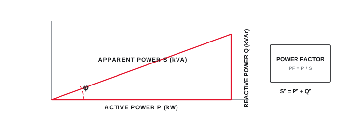
Record active power, reactive power, apparent power and power factor across representative operating states rather than relying on one snapshot.
Capture the connected-load schedule, transformer context, existing capacitor-bank details and the switching sequence used by the installation.
Review voltage and current harmonic measurements before deciding whether conventional capacitor correction is appropriate for the system.
The diagram organizes measurement and decision boundaries; it does not prescribe project ratings or settings.
Final ratings, protection, earthing, settings and interlocks follow approved project engineering.
Open full-size SVGDecision sequence
Identify the bus or feeder whose power factor is being evaluated and the upstream condition the correction is expected to change.
Record kW, kvar and power factor over normal, peak, light-load and rapid-cycle operating combinations.
Review non-linear loads, measured spectra and the condition of existing correction equipment before selecting capacitor architecture.
Evaluate APFC, fast-switched correction, SVG or another response against the measured duty and accepted verification plan.
Engineering boundary
A web guide cannot determine a safe kvar rating, switching method or detuning requirement without project-specific measurements and protection context.
Any indicative calculation must be checked against the actual duty cycle, system impedance, harmonic environment and applicable engineering requirements.
Direct answers
Confirm the electrical boundary, the time period and whether the value represents a full operating profile or only one bill or instantaneous reading.
No. The cause, load variation, existing correction condition, harmonics and location determine whether repair, control changes, APFC, RTPFC, SVG or another action is relevant.
The familiar relationship can provide an indicative steady-state value, but final correction needs actual operating states, switching resolution, harmonics, voltage and system context.