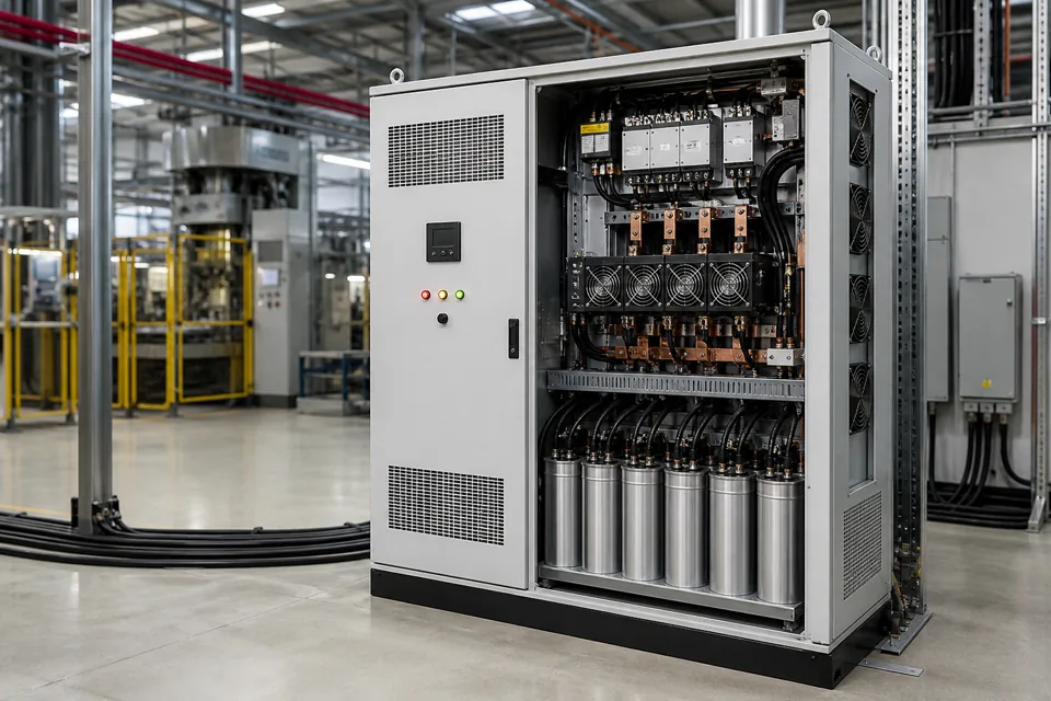
APFC, fast thyristor-switched correction and static VAR generation address reactive-power conditions with different switching, response, thermal and system requirements; selection begins with measured duty rather than a universal ranking.
- Use measured load-change speed and switching frequency as the first discriminator.
- Thyristor switching removes mechanical contact wear but retains capacitor-stage and semiconductor thermal duties.
- An SVG uses power electronics for continuous reactive-current control; harmonic mitigation remains a separate verified function unless explicitly included.
Start with the reactive-load time scale
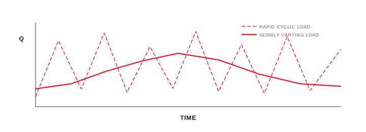
A slowly varying demand can tolerate deliberate contactor steps, while a repetitive fast cycle may require thyristor stages or continuous converter-based control.
Plot the rate and magnitude of kVAr changes during real operating cycles. Contactors are applied where deliberate staged switching and a finite number of mechanical operations fit the duty. Thyristor stages can switch capacitor steps more quickly without mechanical contact bounce, while an SVG controls converter current without discrete capacitor-stage resolution.
Do not infer required response from the machine name alone. Two welding lines, presses or cranes can have different duty cycles, simultaneous operation and source stiffness. Measure at the intended correction boundary.
Evidence basis[1] International Electrotechnical Commission[2] International Electrotechnical Commission
Start with the reactive-load time scale
A slowly varying demand can tolerate deliberate contactor steps, while a repetitive fast cycle may require thyristor stages or continuous converter-based control.
Final ratings, protection, earthing, settings and interlocks follow approved project engineering.
Open full-size SVGCompare discrete stages with continuous control
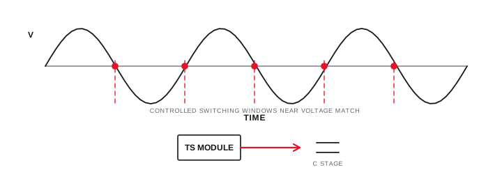
The contactor manages transient making and mechanical life, the thyristor manages controlled capacitor conduction, and the SVG manages converter current and heat.
A capacitor contactor needs suitable making duty and an inrush-control arrangement where specified. A thyristor module uses controlled switching around the network and capacitor voltage relationship, but its losses, heat sink, ventilation, branch protection and failure response require explicit design.
Both capacitor arrangements retain stage-size, discharge, detuning and capacitor-protection decisions. An SVG adds converter rating, current-transformer placement, control mode, thermal derating and integration decisions rather than those capacitor-stage mechanics.
Evidence basis[1] International Electrotechnical Commission[2] International Electrotechnical Commission[3] Eaton
| Decision factor | APFC contactor | RTPFC thyristor | SVG |
|---|---|---|---|
| Correction function | Discrete capacitor steps | Fast discrete capacitor steps | Continuous converter current |
| Primary duty | Mechanical switching | Semiconductor switching and capacitor duty | Converter current and thermal duty |
| Resolution | Selected stage sizes | Selected stage sizes | Within converter control and rating |
| Review focus | Steps, contacts and discharge | Steps, modules, heat and detuning | CTs, controls, cooling and system interaction |
Compare discrete stages with continuous control
The contactor manages transient making and mechanical life, the thyristor manages controlled capacitor conduction, and the SVG manages converter current and heat.
Final ratings, protection, earthing, settings and interlocks follow approved project engineering.
Open full-size SVGDefine the evidence that proves the choice
The accepted technology should meet an agreed response and power-factor objective without abnormal temperature, switching or low-load over-correction.
Define where power factor and kVAr will be measured, the operating states included, the observation window and how blocked stages are handled. Record thermal conditions and controller event history alongside the electrical trend.
If the measured problem is harmonic current rather than rapidly changing displacement reactive power, an AHF or combined strategy may be the relevant branch of the decision. RTPFC is not an active harmonic filter, and an SVG should only be credited with functions explicitly defined and verified for the selected equipment.
Evidence basis[1] International Electrotechnical Commission[4] IEEE Standards Association
Define the evidence that proves the choice
The accepted technology should meet an agreed response and power-factor objective without abnormal temperature, switching or low-load over-correction.

Final ratings, protection, earthing, settings and interlocks follow approved project engineering.
Open full-size SVGInformation that makes the next review more useful.
- 01
Provide time-based kVAr demand with a sampling interval capable of showing the fastest repeated change.
- 02
Record the number of expected correction operations per hour and the required response window.
- 03
Identify harmonics, detuning requirements and capacitor voltage duty.
- 04
Define ambient temperature, ventilation and heat-rejection constraints for switching or converter equipment.
- 05
State maintenance access, spare strategy and acceptable outage for a failed stage.
- 06
Confirm controller logic, capacitor discharge or pre-charge method, stage interlocks and converter interface requirements.
- 07
Define how performance will be measured at the selected electrical boundary.
Standards and technical references.
Links identify the source and scope; access to a complete standard may require purchase or organisational access.
- 01IEC 61921:2017 — Low-voltage power-factor correction banksInternational Electrotechnical Commission
- 02IEC 60831-1:2014 — Low-voltage self-healing shunt power capacitorsInternational Electrotechnical Commission
- 03Application of electromechanical contactors for power-factor correctionEaton
- 04IEEE 519-2022 — Harmonic control in electric power systemsIEEE Standards Association
- 05EasyLogic SVG static VAR generator installation manualSchneider Electric
Questions engineers and project teams ask.
Is RTPFC always better than contactor APFC?
No. Thyristor switching is justified by rapid repetitive demand and the required response. Slower loads can be served effectively by a correctly engineered contactor bank with lower electronic complexity.
Does an SVG replace APFC or an active harmonic filter?
Not universally. The measured reactive-current duty, harmonic objective, response need, thermal context and selected equipment functions determine whether APFC, RTPFC, SVG, AHF or a combined approach is appropriate.