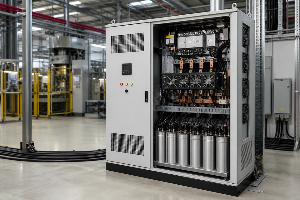
APFC configuration is more dependable when the enquiry includes representative load behaviour, power-factor information, the electrical system and existing correction equipment.
- A monthly average can hide rapid load changes and periods of leading or lagging power factor.
- Capacitor rating and step logic must be reviewed together with harmonic and switching conditions.
- Existing bank condition and actual operating measurements are as important as the nameplate total.
Capture a representative load profile
Power-factor correction follows the combination and timing of active and reactive demand, not one isolated reading.
Record active power, reactive power, apparent power and power factor over intervals that include normal production states, light-load periods, shift changes and known problem events. Tie the measurements to equipment operation so the engineering team can see which loads drive each condition.
If the process changes quickly, an average interval may smooth away the behaviour that determines switching speed and step size. Welders, cranes, compressors and cyclic production equipment can require a different response from a slowly varying base load.
Capture a representative load profile
Power-factor correction follows the combination and timing of active and reactive demand, not one isolated reading.

Final ratings, protection, earthing, settings and interlocks follow approved project engineering.
Open full-size SVGMap the electrical system context
Transformer, feeder and point-of-connection data determine where correction acts and what it can influence.
Share the transformer rating and impedance when available, the relevant bus voltage, upstream and downstream feeders, major motors, drives, generators and any existing capacitor banks. Mark the proposed point of connection on the single-line diagram.
A bank connected at a main bus can improve upstream current and power factor while leaving downstream feeder conditions unchanged. Local correction can affect a particular feeder but introduces different switching, protection and operating considerations.
Map the electrical system context
Transformer, feeder and point-of-connection data determine where correction acts and what it can influence.
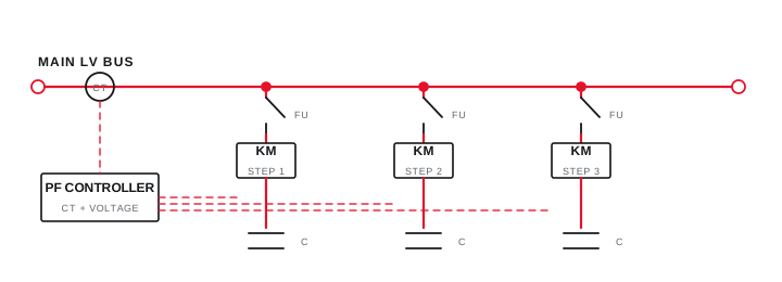
Final ratings, protection, earthing, settings and interlocks follow approved project engineering.
Open full-size SVGRecord harmonics and capacitor condition
Non-linear loads and network resonance can change the correct capacitor-bank architecture.
Identify variable-speed drives, rectifiers, UPS systems, welders and other power-electronic loads even when a formal harmonic survey is not yet available. If measurements exist, include the location, time, load state, voltage distortion and current spectrum.
Inspect the existing bank for failed stages, bulging or leaking units, contactor distress, reactor temperature, ventilation problems and controller alarms. Do not treat a disconnected or degraded bank as evidence that the originally installed rating was correct.
Provide stage ratings, switching devices, reactor data and controller settings where legible.
Record whether the site has experienced fuse operation, nuisance trips, overheating or capacitor failures.
Use an authorised inspection process and de-energised safe-work procedure for internal examination.
Record harmonics and capacitor condition
Non-linear loads and network resonance can change the correct capacitor-bank architecture.
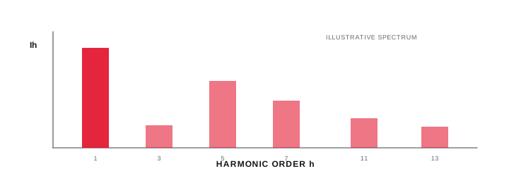
Final ratings, protection, earthing, settings and interlocks follow approved project engineering.
Open full-size SVGInformation that makes the next review more useful.
- 01
Share recent electricity bills or recorded demand and power-factor information where available.
- 02
Provide the single-line diagram, transformer details, system voltage and frequency.
- 03
List major inductive and non-linear loads with their operating combinations and duty cycles.
- 04
Provide time-based power-factor, kW and kVAr measurements if a study has been completed.
- 05
Include harmonic measurements or identify drives, rectifiers, welders and other electronic loads.
- 06
Record existing capacitor-bank capacity, stage sizes, controller and observed condition.
- 07
Describe installation space, ventilation, temperature, dust and cable-entry constraints.
Standards and technical references.
Links identify the source and scope; access to a complete standard may require purchase or organisational access.
- 01IEC 60831-1:2014 — Low-voltage self-healing shunt power capacitorsInternational Electrotechnical Commission
- 02IEC 61921:2017 — Low-voltage power-factor correction banksInternational Electrotechnical Commission
- 03Technology compendium — Automatic power-factor controllerBureau of Energy Efficiency, Government of India
Questions engineers and project teams ask.
Is a monthly power-factor value enough for APFC selection?
It may indicate a concern but can hide rapid or shift-based changes. Time-based measurements and the operating load profile usually provide a better basis for step and switching decisions.
Why list non-linear loads in an APFC enquiry?
Drives, rectifiers, welders and other power-electronic loads can influence harmonic conditions and the suitability of conventional, detuned or dynamic correction approaches.