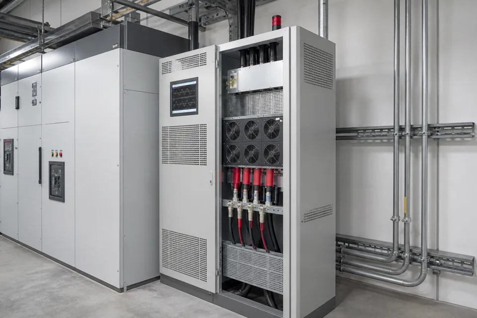
VFD harmonic mitigation should follow measured or modelled system behaviour at a defined boundary, not a device label or one current-THD number viewed in isolation.
- Current distortion at one drive terminal is not interchangeable with voltage distortion at the PCC.
- Source impedance and the simultaneous drive operating pattern influence system response.
- Mitigation should have a boundary-specific acceptance method before equipment is selected.
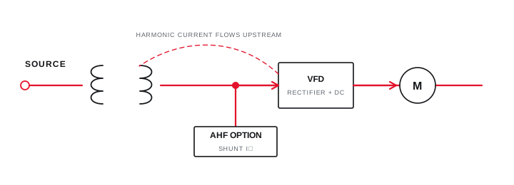
Define the complete drive and network boundary
Drive topology, source impedance and other connected equipment determine the system context for harmonics.
Record the drive front end, any input reactor or filter, motor load cycle and the number of drives operating together. Add transformer data, capacitor banks, generators and other nonlinear loads that share the relevant bus.
IEC 61800-3 addresses EMC requirements for power-drive systems, while a PCC harmonic assessment needs the applicable system-level objective and measurement boundary.
Evidence basis[1] International Electrotechnical Commission[2] International Electrotechnical Commission[3] IEEE Standards Association
Define the complete drive and network boundary
Drive topology, source impedance and other connected equipment determine the system context for harmonics.
Final ratings, protection, earthing, settings and interlocks follow approved project engineering.
Open full-size SVGMeasure representative operating states and spectra
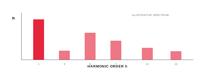
Time trends and harmonic spectra show how distortion changes with drive loading and system configuration.
Capture voltage and current at the defined locations with synchronised operating notes. Include low, normal and relevant high-load states, and identify whether capacitor stages or generators changed during the record.
Report fundamental current alongside current THD, and harmonic voltage alongside the defined bus condition. A large percentage at very low current can answer a different question from the maximum absolute harmonic current.
Evidence basis[2] International Electrotechnical Commission[3] IEEE Standards Association
Measure representative operating states and spectra
Time trends and harmonic spectra show how distortion changes with drive loading and system configuration.
Final ratings, protection, earthing, settings and interlocks follow approved project engineering.
Open full-size SVGSelect and verify mitigation against the objective
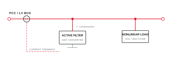
Reactors, passive filters, active filters and drive-front-end changes have different boundaries and interactions.
Screen each option for the measured orders, load variation, source impedance, capacitor interaction, losses and maintenance needs. Do not treat a percentage reduction from a brochure as a guaranteed site result.
Define a post-installation measurement plan at the same boundary, using comparable operating states and documented instrument settings.
Evidence basis[1] International Electrotechnical Commission[2] International Electrotechnical Commission[3] IEEE Standards Association
Select and verify mitigation against the objective
Reactors, passive filters, active filters and drive-front-end changes have different boundaries and interactions.
Final ratings, protection, earthing, settings and interlocks follow approved project engineering.
Open full-size SVGInformation that makes the next review more useful.
- 01
List drive topology, rating, input components, motor duty and normal speed or torque range.
- 02
Map the source transformer, parallel nonlinear loads, capacitor banks and proposed measurement boundary.
- 03
Record voltage and current spectrum with time trends across representative operating states.
- 04
Capture source impedance or short-circuit information used by the assessment.
- 05
Define whether the objective concerns PCC limits, equipment duty, resonance or local waveform quality.
- 06
Compare mitigation options against the measured spectrum and operating envelope.
- 07
Plan post-change verification at the same boundary and representative states.
Standards and technical references.
Links identify the source and scope; access to a complete standard may require purchase or organisational access.
Questions engineers and project teams ask.
Is high current THD at a VFD terminal automatically a PCC violation?
No. Device-terminal current distortion and system PCC criteria use different boundaries and context. The applicable objective, demand current and measurement method must be established.
Should a harmonic filter be selected before taking measurements?
For a brownfield system, representative measurement and source data reduce the risk of selecting equipment for the wrong orders, loading pattern or electrical boundary.