
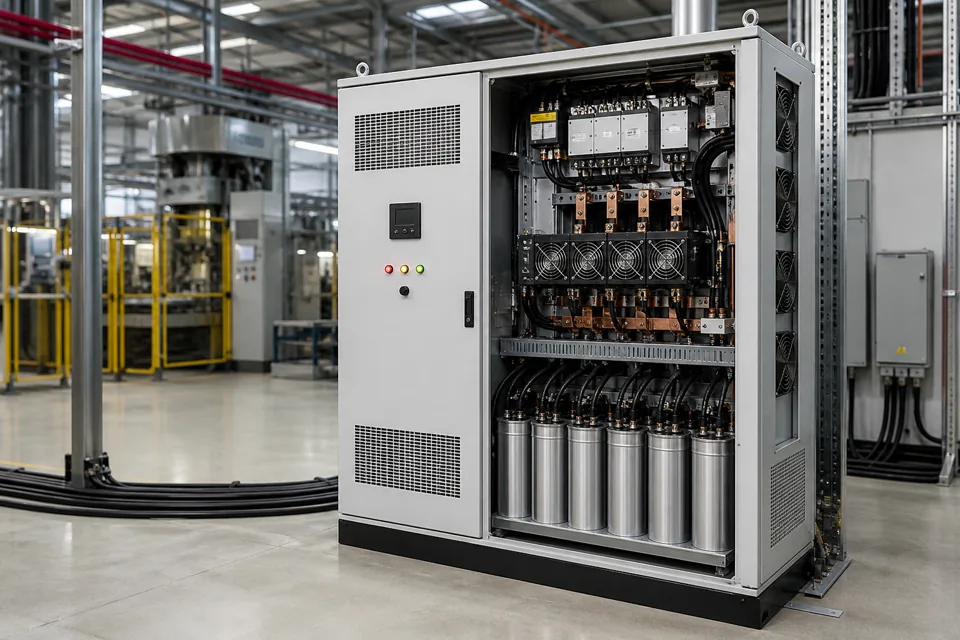
Thyristor-switched APFC replaces mechanical stage switching with controlled semiconductor switching for fast, repeatable discrete reactive compensation.
- Thyristor switching is appropriate when mechanical switching and discharge delays cannot follow the reactive-load cycle.
- Controlled switching reduces switching transients only when voltage sensing, timing and branch conditions are correct.
- The bank remains discrete: stage size still determines correction resolution.
- Semiconductor losses and reactor losses make thermal design a first-order requirement.
Identify a genuinely dynamic application
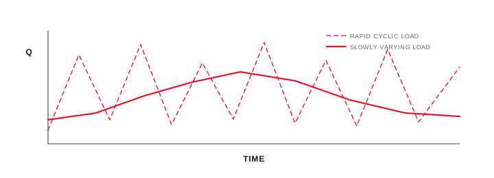
Rapid correction should be justified by the reactive-load waveform and the business or process consequence of slow response.
Capture reactive demand at a time resolution that shows the cycle. Welding, cranes, presses, elevators and other intermittent equipment can change more quickly than a contactor bank should switch, but not every site containing those loads needs the same solution.
Define whether the objective is to avoid a tariff interval penalty, reduce reactive current during each cycle, stabilise a local bus or improve a measured process condition. The objective determines the required response and verification.
Identify a genuinely dynamic application
Rapid correction should be justified by the reactive-load waveform and the business or process consequence of slow response.
Final ratings, protection, earthing, settings and interlocks follow approved project engineering.
Open full-size SVGUnderstand controlled zero-cross switching
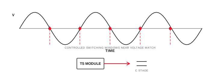
The controller connects a capacitor stage when the voltage relationship minimises the switching transient, then removes it under controlled conditions.
A thyristor module does not make arbitrary switching safe. It requires correct phase reference, synchronisation, gating, protection and a branch whose residual voltage and reactor-capacitor behaviour are understood.
Unlike a mechanical contactor, the semiconductor conducts with continuous losses while the stage is on. Heat sinks, airflow, temperature monitoring and enclosure design are therefore integral to the rating.
Understand controlled zero-cross switching
The controller connects a capacitor stage when the voltage relationship minimises the switching transient, then removes it under controlled conditions.
Final ratings, protection, earthing, settings and interlocks follow approved project engineering.
Open full-size SVGEngineer the complete dynamic bank
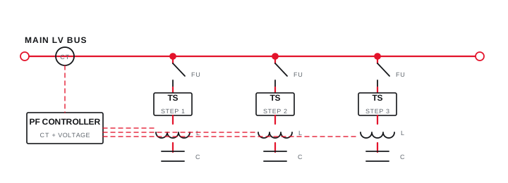
Fast switching, detuning, protection and stage logic must operate as one coordinated system.
Stage resolution follows the minimum meaningful reactive increment, while the total range follows representative peak demand. The controller should avoid chattering between adjacent combinations and should recognise unavailable or failed stages.
Review capacitor and reactor duty under measured harmonics, semiconductor fault protection, incoming and branch protection, control-power continuity, thermal alarms and safe isolation for maintenance.
Engineer the complete dynamic bank
Fast switching, detuning, protection and stage logic must operate as one coordinated system.
Final ratings, protection, earthing, settings and interlocks follow approved project engineering.
Open full-size SVGInformation that makes the next review more useful.
- 01
Time-resolved kW, kVAr and power-factor profile across rapid load cycles.
- 02
Maximum acceptable response time and residual reactive-power variation.
- 03
Switching frequency and expected operations over the equipment life.
- 04
Harmonic spectrum, detuning requirement and system impedance data.
- 05
Ambient, ventilation and semiconductor heat-rejection conditions.
- 06
Control supply, CT location, stage feedback and alarm requirements.
Standards and technical references.
Links identify the source and scope; access to a complete standard may require purchase or organisational access.
- 01IEC 61921:2017 — Low-voltage power-factor correction banksInternational Electrotechnical Commission
- 02IEC 60831-1:2014 — Low-voltage self-healing shunt power capacitorsInternational Electrotechnical Commission
- 03IEC 61642:1997 — Filters and shunt capacitors in harmonic-affected networksInternational Electrotechnical Commission
Questions engineers and project teams ask.
Is thyristor APFC the same as a static VAR generator?
No. Thyristor APFC switches discrete capacitor-reactor stages quickly. An SVG uses a power-electronic converter for continuously variable reactive-current compensation within its rating.
Can thyristor switching eliminate capacitor inrush completely?
Controlled switching can greatly reduce transients when correctly coordinated, but branch parameters, residual voltage, timing, protection and system conditions still require engineering verification.


