

SVG commissioning proves that the converter measures the intended boundary, applies reactive current in the correct direction and respects configured limits.
- Reactive-power sign and CT orientation must be proven before automatic control.
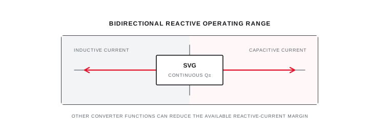
- The selected control priority can reserve converter current for functions other than power-factor correction.
- Commissioning evidence should compare source-side response under named load conditions.
Freeze the control objective and sign convention
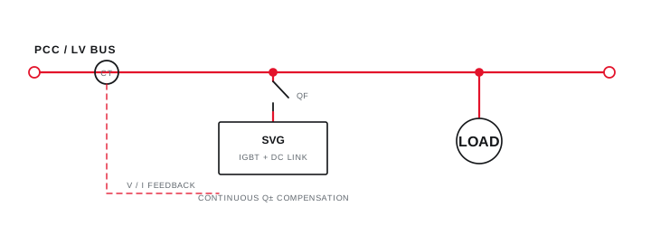
Target power factor, reactive power or voltage mode must be tied to one named measurement boundary.
Record whether the project targets source-side power factor, reactive power, voltage support or a coordinated multi-function priority. Define leading and lagging sign conventions in the commissioning sheet.
Trace CT and voltage references from the single-line to the converter terminals. Include tie, generator and parallel-source states that could move or invalidate the measurement boundary.
Evidence basis[1] International Electrotechnical Commission[2] International Electrotechnical Commission
Freeze the control objective and sign convention
Target power factor, reactive power or voltage mode must be tied to one named measurement boundary.
Final ratings, protection, earthing, settings and interlocks follow approved project engineering.
Open full-size SVGProve reactive-current direction at a limited command
A small controlled response can expose polarity or phase errors before full automatic operation.
Capture baseline kW, kVAr, current and power factor with the SVG disabled. Apply an approved limited command and verify that source-side reactive power moves in the intended direction while phase currents remain credible.
If the response is reversed, oscillatory or unbalanced, stop and verify CT polarity, phase association, voltage sequence and configured sign convention before increasing output.
Evidence basis[1] International Electrotechnical Commission[2] International Electrotechnical Commission[3] International Electrotechnical Commission
Prove reactive-current direction at a limited command
A small controlled response can expose polarity or phase errors before full automatic operation.
Final ratings, protection, earthing, settings and interlocks follow approved project engineering.
Open full-size SVGRelease automatic control with limit evidence
Representative load changes should show response, stability, alarms and remaining converter-current margin.
Observe the controller through repeated load transitions and confirm target, response time, deadband and current limits against the approved configuration. Record any active harmonic or imbalance function sharing converter capacity.
Retain final settings, baseline and enabled trends, event times, alarm checks and bypass procedure. Product instructions remain authoritative for safety, service and the selected converter's actual functions.
Evidence basis[1] International Electrotechnical Commission[2] International Electrotechnical Commission[3] International Electrotechnical Commission
| Step | Observation | Release condition |
|---|---|---|
| Baseline | Source kVAr and power factor | Stable named load state |
| Limited command | Correct reactive direction | No phase or polarity error |
| Automatic response | Target and stability | Within configured limits |
| Headroom | Converter current allocation | Constraint documented |
Information that makes the next review more useful.
- 01
Confirm the compensation objective, measurement boundary and target variable from approved documents.
- 02
Verify CT location, ratio, polarity, phase mapping and voltage-reference sequence.
- 03
Record cable, protection, fault level, ventilation, earthing and manufacturer installation checks.
- 04
Capture baseline kW, kVAr, power factor, current and voltage with the converter disabled.
- 05
Command a limited reactive-current response and verify the source-side sign and magnitude direction.
- 06
Observe automatic response through representative load changes without exceeding approved limits.
- 07
Retain final parameters, trends, alarms, current headroom, fallback and untested operating states.
Standards and technical references.
Links identify the source and scope; access to a complete standard may require purchase or organisational access.
- 01IEC 62477-1:2022 — Safety requirements for power electronic converter systemsInternational Electrotechnical Commission
- 02IEC 61000-4-30:2025 — Power-quality measurement methodsInternational Electrotechnical Commission
- 03IEC 61000-2-4:2024 — Compatibility levels for industrial power-distribution systemsInternational Electrotechnical Commission
Questions engineers and project teams ask.
What should be checked before enabling an SVG in automatic mode?
Confirm the objective, CT and voltage references, sign convention, phase mapping, baseline measurements, protection, limits and a successful limited-direction test.
Why might an SVG not reach the target power factor?
Available converter current, control priorities, CT boundary, load dynamics, voltage conditions or configured limits can constrain the source-side result.




