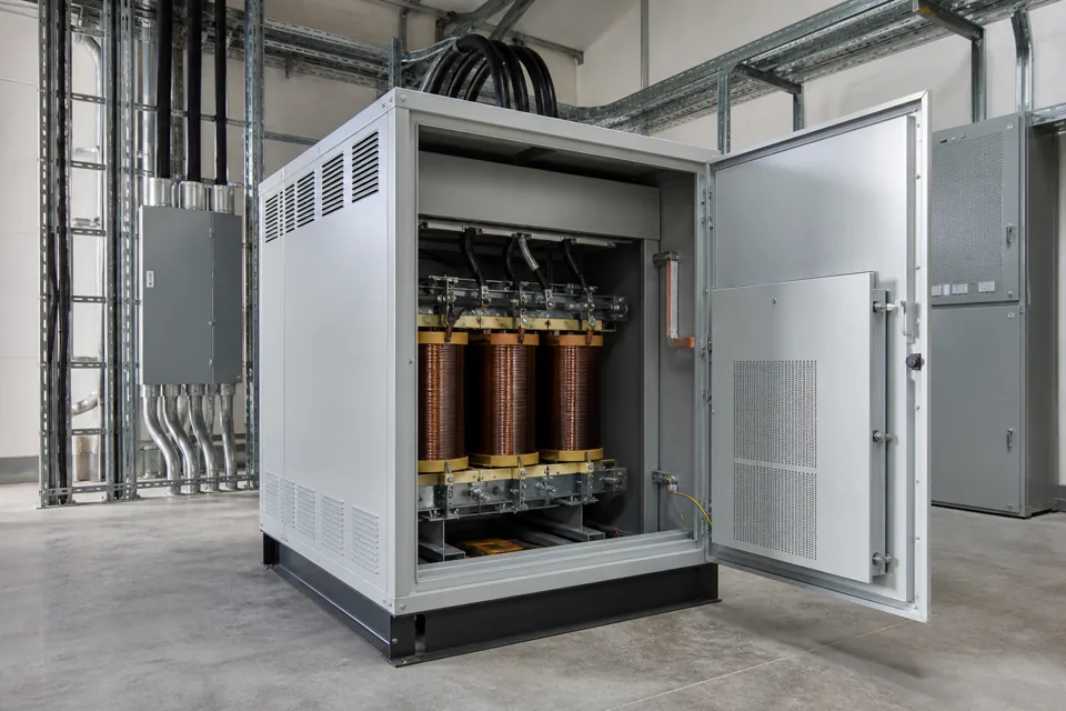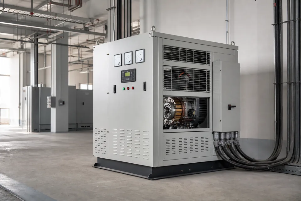
A servo stabilizer regulates sustained input-voltage variation through a controlled buck-boost arrangement, within a defined range, response and load duty.
- A stabilizer addresses sustained voltage variation within its design range; it is not an interruption or deep-dip ride-through source.
- Input-current duty can rise at low input voltage for the same output power and must be included in rating.
- Load starting and rapid steps can exceed steady-state kVA and response assumptions.
- Bypass and protection should preserve a clear operating mode and avoid uncontrolled parallel paths.
Classify the voltage condition first
Separate sustained variation from dips, swells, interruptions, unbalance and transient events before selecting regulation equipment.
Record phase-to-phase and, where relevant, phase-to-neutral voltage over representative production periods. Tie excursions to source transfers, large motor starts, utility conditions and load changes.
IEC 61000-4-30 defines methods for several power-quality parameters, including voltage magnitude, dips, swells, interruptions and unbalance. The selected stabilizer must match the phenomenon it can actually regulate.
Classify the voltage condition first
Separate sustained variation from dips, swells, interruptions, unbalance and transient events before selecting regulation equipment.

Final ratings, protection, earthing, settings and interlocks follow approved project engineering.
Open full-size SVGMatch rating to input range and load duty
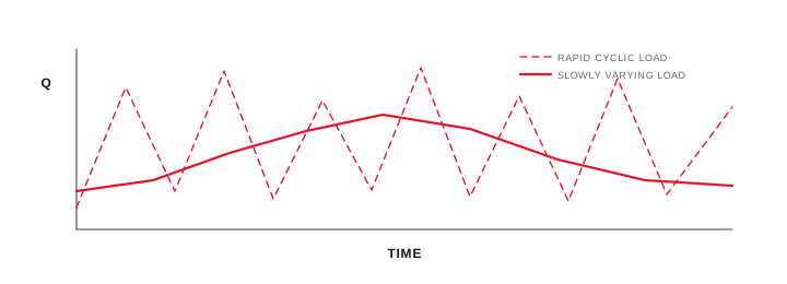
The same load can demand more input current at the low end of the permitted voltage range, while motor and transformer inrush add short-duration duty.
Use maximum simultaneous output kVA and the stabilizer efficiency and input range to check current at worst-case voltage. Include load power factor, harmonic current, starting and cyclic overloads rather than using connected kW as the only input.
Define whether all three phases are corrected together or independently, and verify the connected equipment can tolerate the response and residual deviation during rapid load changes.
Match rating to input range and load duty
The same load can demand more input current at the low end of the permitted voltage range, while motor and transformer inrush add short-duration duty.
Final ratings, protection, earthing, settings and interlocks follow approved project engineering.
Open full-size SVGEngineer bypass, protection and operating modes
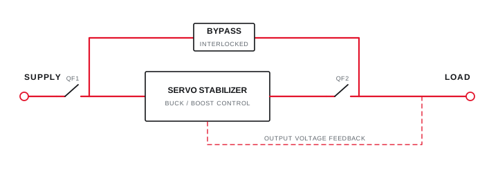
A maintenance bypass keeps the load path explicit and interlocked while the stabilising section is isolated according to the approved design.
Specify input, output and bypass switching, electrical or mechanical interlocks, surge protection where required, overvoltage and undervoltage response, overload protection and phase-failure behaviour.
Define alarms, metering, remote indications and the state after control-power recovery. Acceptance tests should cover representative input extremes and load steps within a safe approved test arrangement.
Engineer bypass, protection and operating modes
A maintenance bypass keeps the load path explicit and interlocked while the stabilising section is isolated according to the approved design.
Final ratings, protection, earthing, settings and interlocks follow approved project engineering.
Open full-size SVGInformation that makes the next review more useful.
- 01
Minimum, maximum and typical input voltage with timestamps and operating state.
- 02
Required output range and the connected equipment tolerance.
- 03
Maximum simultaneous kVA, current, power factor, inrush and load steps.
- 04
Three-phase unbalance and whether independent phase correction is required.
- 05
Response expectation, bypass philosophy and protection coordination.
- 06
Ambient, enclosure, cooling, cable entry and maintenance access.
Standards and technical references.
Links identify the source and scope; access to a complete standard may require purchase or organisational access.
- 01IEC 61000-4-30:2025 — Power-quality measurement methodsInternational Electrotechnical Commission
- 02Central Electricity Authority safety and electric-supply regulations, 2023Central Electricity Authority, Government of India
- 03IEC 61439-1:2020 — General rules for low-voltage assembliesInternational Electrotechnical Commission
Questions engineers and project teams ask.
Can a servo stabilizer prevent every voltage dip?
No. A stabilizer has a defined correction range and response. Short or deep dips, interruptions and source failures may require ride-through, UPS, source or system measures after a separate assessment.
Why can stabilizer input current be higher at low voltage?
For similar output power, lower input voltage generally requires higher input current after efficiency and control limits are considered. The incoming device, conductors and stabilizer rating must cover that duty.