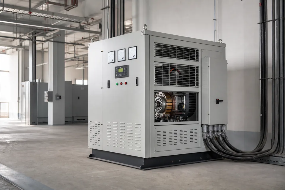
A stabilizer selection should be based on measured input variation and load behaviour, with transients and internal load-generated events kept distinct.
- Voltage range, duration and load state belong in the same survey record.
- A stabilizer does not correct every upstream interruption or downstream load-generated event.
- Input envelope, output objective and bypass state define the selection boundary.
Define input, output and load measurement boundaries
Measurements should show what reaches the stabilizer and what the protected load actually experiences.
Place instruments at the proposed input and, where needed, the sensitive load boundary. Record conductor and transformer paths between them so voltage drop is not mistaken for a supply deviation.
IEC 60038 provides standard voltage reference values. Actual compatibility and contractual supply conditions require the applicable local and project criteria.
Evidence basis[1] International Electrotechnical Commission[2] International Electrotechnical Commission
Define input, output and load measurement boundaries
Measurements should show what reaches the stabilizer and what the protected load actually experiences.
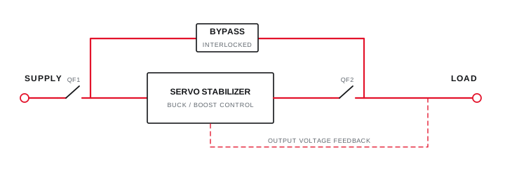
Final ratings, protection, earthing, settings and interlocks follow approved project engineering.
Open full-size SVGBuild a time-based voltage and load envelope
Interval trends and event records distinguish sustained range from short disturbances.
Trend phase voltages, current, kW, kVAr and imbalance, then capture dips, swells and interruptions with duration and timestamp. Link every significant event to motor starting, generator transfer, switching or production state where possible.
IEC 61000-4-30 defines measurement methods for multiple power-quality parameters. State instrument class and aggregation when the data supports a formal comparison.
Evidence basis[2] International Electrotechnical Commission[3] International Electrotechnical Commission
Build a time-based voltage and load envelope
Interval trends and event records distinguish sustained range from short disturbances.
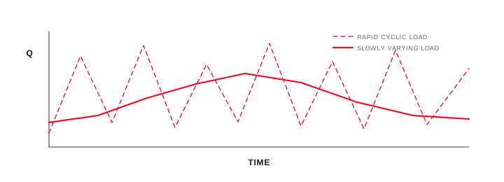
Final ratings, protection, earthing, settings and interlocks follow approved project engineering.
Open full-size SVGSelect the complete stabilizer and bypass system
Range and kVA must be coordinated with starting duty, regulation objective and system fault conditions.
Provide the measured minimum and maximum, duration distribution, phase imbalance, load profile, starting duty and harmonic content to the manufacturer. Confirm available output at the most severe input state rather than only nominal kVA.
Define automatic or maintenance bypass, neutral treatment, protection, cable duty, enclosure and ventilation. Commission with input and output trends under representative load and record states outside the witnessed envelope.
Evidence basis[1] International Electrotechnical Commission[2] International Electrotechnical Commission[3] International Electrotechnical Commission
| Observation | Selection question | Limitation |
|---|---|---|
| Sustained range | Buck and boost capability | Needs load correlation |
| Dip or interruption | Ride-through expectation | May need another technology |
| Starting event | Dynamic voltage response | Source dependent |
| Bypass state | Continuity and protection | Separate operating mode |
Information that makes the next review more useful.
- 01
Measure three-phase input voltage, current, power and imbalance over representative operating cycles.
- 02
Capture dips, swells, interruptions and rapid changes with their duration and active load state.
- 03
Separate utility variation from voltage drop, motor starting and internal switching events.
- 04
List continuous, peak, starting and future load with power factor and harmonic content.
- 05
Define acceptable output range, response expectation and loads that must not be interrupted.
- 06
Confirm bypass, isolation, neutral, earthing, fault level, ventilation and maintenance access.
- 07
Validate final range and kVA against manufacturer capability using the measured envelope.
Standards and technical references.
Links identify the source and scope; access to a complete standard may require purchase or organisational access.
- 01IEC 60038:2009+AMD1:2021 — IEC standard voltagesInternational Electrotechnical Commission
- 02IEC 61000-2-4:2024 — Compatibility levels for industrial power-distribution systemsInternational Electrotechnical Commission
- 03IEC 61000-4-30:2025 — Power-quality measurement methodsInternational Electrotechnical Commission
Questions engineers and project teams ask.
Can a servo stabilizer correct a complete power interruption?
No. A stabilizer regulates within its designed input and dynamic range; interruption ride-through normally requires a different source or stored-energy arrangement.
How long should a voltage survey run before stabilizer selection?
Long enough to capture representative production, low-load, starting and source-transfer states. The required duration depends on how often the important events occur.