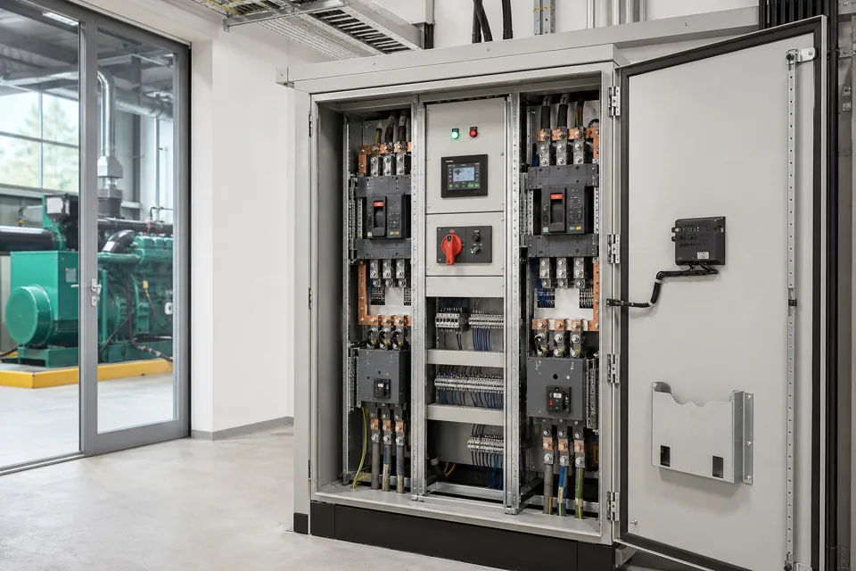
LV protection and selectivity decisions require the source fault level, conductor withstand, load duty and exact protective-device characteristics; panel current alone cannot define them.
- Breaking capacity, conductor protection and selectivity are related but distinct checks.
- Exact device characteristics and settings are required; generic breaker labels are insufficient.
- State the selectivity current range and operating configuration rather than claiming absolute discrimination.
Build the source-to-fault current path
Every source, transformer, cable and bus impedance between generation and the fault changes the prospective current and protection duty.
Model normal utility, generator, bus-coupler and parallel-source configurations separately. A device that has adequate breaking capacity on one isolated transformer can face a different duty when sources are paralleled or a bus tie is closed.
Carry the calculation to important downstream points using the actual conductor and transformer data. Record assumptions and data provenance so later source or cable changes trigger a review.
Evidence basis[1] International Electrotechnical Commission[2] International Electrotechnical Commission
Build the source-to-fault current path
Every source, transformer, cable and bus impedance between generation and the fault changes the prospective current and protection duty.

Final ratings, protection, earthing, settings and interlocks follow approved project engineering.
Open full-size SVGCompare exact device characteristics and load duty
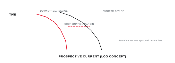
Time-current curves, instantaneous thresholds, current-limiting data and manufacturer selectivity tables are combination-specific.
Plot downstream conductor and equipment withstand with the protective-device characteristics. Include motor start, transformer inrush or other accepted operating current so settings do not trade nuisance operation for inadequate protection without a documented decision.
Use the current manufacturer's coordination data for the exact upstream and downstream devices. Selectivity can be full to a stated current or partial below a defined level; report that boundary explicitly.
Evidence basis[1] International Electrotechnical Commission[3] International Electrotechnical Commission
Compare exact device characteristics and load duty
Time-current curves, instantaneous thresholds, current-limiting data and manufacturer selectivity tables are combination-specific.
Final ratings, protection, earthing, settings and interlocks follow approved project engineering.
Open full-size SVGTurn the study into controlled settings evidence
Approved settings, installed labels, test records and change control connect the coordination decision to the physical panel.
Issue a settings schedule with device identity, function, current and time settings, seal or access control, and the study revision. Verify the installed trip unit and rating plug before accepting the setting record.
Commissioning tests should follow the device and project method. A secondary-injection or functional trip test confirms selected parts of the chain; it does not reproduce every high-current fault condition.
Evidence basis[1] International Electrotechnical Commission[2] International Electrotechnical Commission[3] International Electrotechnical Commission
Information that makes the next review more useful.
- 01
Provide utility, transformer, generator and parallel-source data for every normal configuration.
- 02
Record calculated prospective short-circuit current at the incomer and important downstream buses.
- 03
List exact protective-device make, model, trip unit, rating plug, settings and firmware where relevant.
- 04
Provide conductor type, size, length, installation method and thermal and short-circuit withstand basis.
- 05
Record motor starting, transformer inrush, drive or UPS behaviour and other legitimate high-current states.
- 06
Define the circuits where full, partial or no selectivity is required and why.
- 07
Use current manufacturer curves, tables or approved software for the selected device combination.
Standards and technical references.
Links identify the source and scope; access to a complete standard may require purchase or organisational access.
Questions engineers and project teams ask.
Can breaker selectivity be confirmed from frame sizes alone?
No. It depends on exact devices, trip units, settings, fault-current range and manufacturer coordination data. Larger upstream frame size does not by itself prove discrimination.
Does a protection study remain valid after the transformer changes?
Not automatically. Transformer rating or impedance changes can alter prospective current and the coordination boundary. The model and settings should be reviewed against the revised source data.