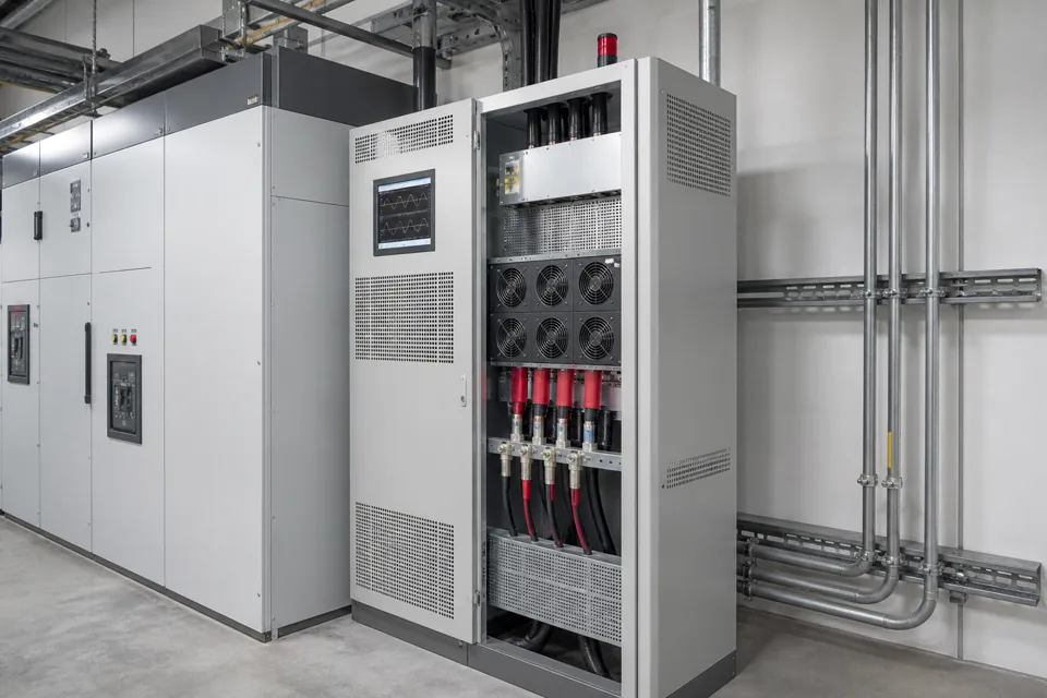
A useful power-quality measurement plan links one testable symptom to selected electrical boundaries, synchronized instruments and an operating-state log before data collection begins.
- Start with a testable question, not a generic request to measure power quality.
- Time alignment between electrical trends and operating events is essential for causal interpretation.
- Instrument class, transducers and connection boundaries belong in the evidence record.
Convert the symptom into a measurement question
A clear question limits parameters and locations to those capable of confirming or excluding a plausible cause.
Replace broad descriptions such as 'voltage problem' with a timed observation: which equipment changed state, what protection or control reacted, how long it lasted and whether other loads were affected. This separates voltage magnitude, interruption, transient, unbalance, harmonic and control-interface hypotheses.
Mark the source and affected path on the single-line diagram. A measurement at the wrong bus can miss the event or combine unrelated feeders into one trace.
Evidence basis[1] International Electrotechnical Commission[2] IEEE Standards Association
Convert the symptom into a measurement question
A clear question limits parameters and locations to those capable of confirming or excluding a plausible cause.

Final ratings, protection, earthing, settings and interlocks follow approved project engineering.
Open full-size SVGMatch instruments and locations to the question
Class, range, transducers, sampling and aggregation method determine which comparisons the captured data can support.
IEC 61000-4-30 defines repeatable methods for parameters including frequency, voltage magnitude, dips, swells, interruptions, unbalance, harmonics and current. Class A supports comparable measurements where disputes or formal assessment may matter; Class S supports survey work with a different purpose and performance boundary.
Document every inserted CT, VT and probe because its ratio, bandwidth, phase error and installation influence the result. Use approved connection and isolation procedures for the actual system voltage and fault level.
Evidence basis[1] International Electrotechnical Commission[3] Central Electricity Authority, Government of India
Match instruments and locations to the question
Class, range, transducers, sampling and aggregation method determine which comparisons the captured data can support.

Final ratings, protection, earthing, settings and interlocks follow approved project engineering.
Open full-size SVGBuild a shared time and operating-state record
Synchronized analyser clocks and a disciplined event log allow voltage, current, production and switching changes to be compared without guessing.
Record shift, production mode, major load starts, drive changes, capacitor switching, source transfers, generator operation and operator observations using one time base. Where several analysers are used, confirm clock alignment before installation and after retrieval.
State what the measurement period did not include. A week without the fault-producing batch, seasonal load or utility event cannot prove those states are acceptable; it only describes the observed window.
Evidence basis[1] International Electrotechnical Commission[2] IEEE Standards Association
| Record | Example content | Why retained |
|---|---|---|
| Boundary | PCC, affected bus, feeder | Fixes interpretation location |
| Instrument | Class, range, firmware | Defines method capability |
| Operating log | Load and switching states | Correlates cause and effect |
| Limitations | Missing states or failed channels | Prevents over-claiming |
Information that makes the next review more useful.
- 01
Write the observed symptom with time, equipment state, frequency and consequence.
- 02
Mark the source, PCC, affected bus and candidate load feeders on the latest single-line diagram.
- 03
Choose voltage, current, power, unbalance, event and harmonic parameters relevant to the question.
- 04
Record instrument class, firmware, range, probes, CTs, VTs and connection method.
- 05
Synchronize analyser clocks and create an operating and event log with responsible owners.
- 06
Define installation safety, permits, PPE, access and removal procedure before field work.
- 07
Agree the observation window, comparable operating states and report limitations.
Standards and technical references.
Links identify the source and scope; access to a complete standard may require purchase or organisational access.
- 01IEC 61000-4-30:2025 — Power-quality measurement methodsInternational Electrotechnical Commission
- 02IEEE 519-2022 — Harmonic control in electric power systemsIEEE Standards Association
- 03Central Electricity Authority safety and electric-supply regulations, 2023Central Electricity Authority, Government of India
Questions engineers and project teams ask.
How long should an industrial power-quality survey run?
Long enough to capture the operating states relevant to the question. Duration is set from production cycles, event frequency and assessment purpose; a default week may still miss a rare or seasonal condition.
Why use more than one measurement location?
Synchronized locations can show whether an event arrives from the source, develops on an internal bus or follows a load feeder. The added points should be chosen from a clear hypothesis and safe connection plan.