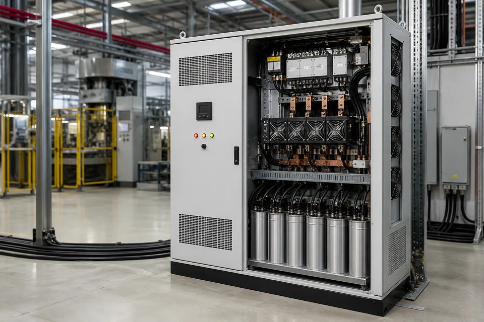
Capacitor condition cannot be reduced to one capacitance reading; the decision should combine physical evidence, branch behaviour, protection history and operating stress.
- Nameplate and service history establish the baseline for any condition decision.
- Capacitance, current balance and visual evidence answer different questions and should not be substituted for one another.
- The branch should be assessed as a function, including switching, protection and discharge components.
Establish the component and duty baseline
Condition evidence has meaning only when tied to the installed rating and the stress the capacitor has experienced.
Record rated voltage, kVAr, frequency, connection and manufacturer data before interpreting a measurement. Then add operating voltage, harmonic environment, ambient temperature, switching frequency and any known overcurrent or fuse event.
For a mixed-age bank, retain the identity of each unit or branch. An average value can conceal one degraded element and can make later trending impossible.
Evidence basis[1] International Electrotechnical Commission[2] International Electrotechnical Commission
Establish the component and duty baseline
Condition evidence has meaning only when tied to the installed rating and the stress the capacitor has experienced.
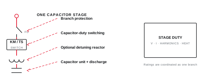
Final ratings, protection, earthing, settings and interlocks follow approved project engineering.
Open full-size SVGCombine physical, electrical and operational evidence
No single inspection method provides a complete view of dielectric, connection and branch performance.
Physical deformation, leakage or terminal damage can justify removal from service without further energisation. Where direct measurements are permitted, compare them with component information and the chosen test method rather than using an invented universal threshold.
During authorised operation, phase current, reactive contribution and temperature pattern can identify imbalance or a branch that does not deliver the expected function. Note the bus voltage and energised stage configuration with every observation.
Evidence basis[1] International Electrotechnical Commission[2] International Electrotechnical Commission[3] International Electrotechnical Commission
Combine physical, electrical and operational evidence
No single inspection method provides a complete view of dielectric, connection and branch performance.
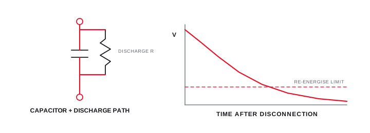
Final ratings, protection, earthing, settings and interlocks follow approved project engineering.
Open full-size SVGMake a documented branch-level disposition
The closeout identifies what can return to service, what needs further test and what should remain isolated.
Separate confirmed defects from suspected degradation. A branch may need investigation because of a failed switch, blown protection or wiring problem even when the capacitor itself has not been proven defective.
Retain readings, photographs, instrument identification, test conditions and the decision authority. That record supports later trend comparison and prevents a replacement from erasing the original failure evidence.
Evidence basis[1] International Electrotechnical Commission[2] International Electrotechnical Commission[3] International Electrotechnical Commission
Information that makes the next review more useful.
- 01
Capture manufacturer, type, rated voltage, kVAr, frequency, serial or batch data and service age where known.
- 02
Review alarm, fuse, switching and replacement history for the complete branch.
- 03
Apply the approved isolation, discharge and voltage-verification method before direct testing.
- 04
Inspect for deformation, leakage, corrosion, damaged terminals and abnormal thermal evidence.
- 05
Measure only with suitable equipment and compare against documented component or project criteria.
- 06
Check branch current balance and reactive contribution under a defined authorised operating state.
- 07
Record limitations and disposition for the capacitor, switch, protection and discharge path together.
Standards and technical references.
Links identify the source and scope; access to a complete standard may require purchase or organisational access.
- 01IEC 60831-1:2014 — Low-voltage self-healing shunt power capacitorsInternational Electrotechnical Commission
- 02IEC 61921:2017 — Low-voltage power-factor correction banksInternational Electrotechnical Commission
- 03IEC 60364-6:2016 — Verification of low-voltage installationsInternational Electrotechnical Commission
Questions engineers and project teams ask.
Does one capacitance reading prove a power capacitor is serviceable?
No. The reading needs a defined method and criterion, and it should be considered with physical condition, branch current, operating history, protection and switching evidence.
Should a visibly swollen or leaking capacitor be energised for confirmation?
A visible defect should be handled through the site safety and component disposition process. Do not energise damaged equipment merely to obtain another data point.