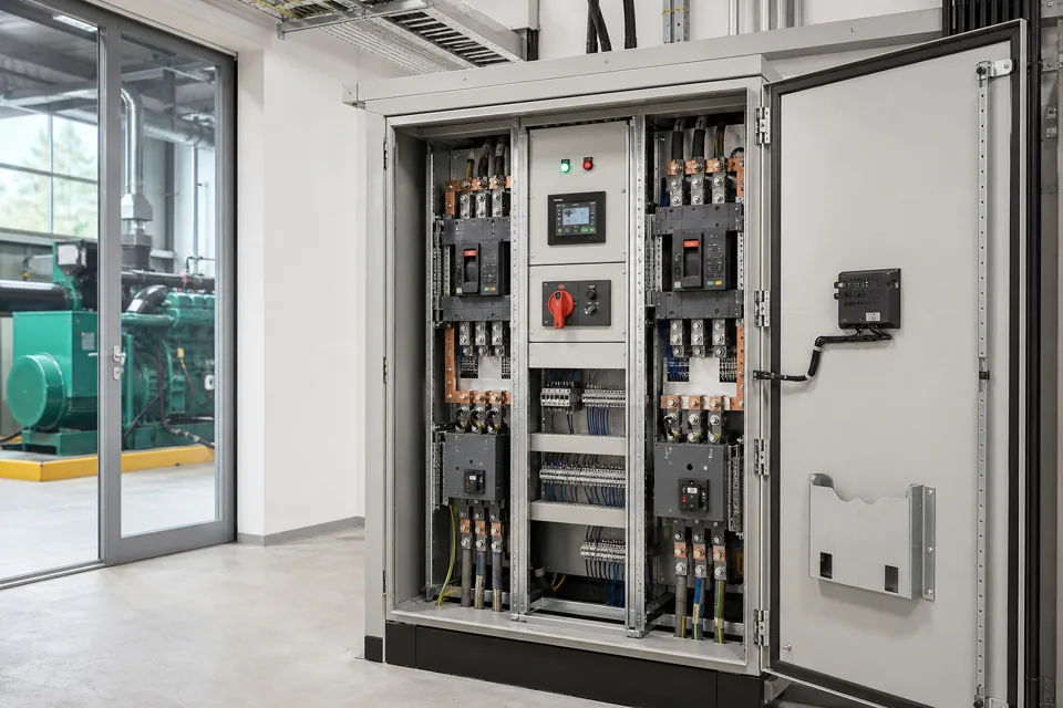
PLC I/O commissioning proves the chain from field device and terminal to software tag, engineering value, alarm, command and safe operating response.
- A channel indication, engineering value and process response are separate test layers.
- The accepted control narrative defines what a proven I/O state should cause.
- Forces and temporary bypasses require an explicit register and closeout.
Freeze the test baseline and signal identity
Drawing, tag, software and device revisions must point to the same commissioned object.
Record the I/O list, terminal drawings, field-device schedule, cause-and-effect matrix and PLC programme checksum or revision. Resolve duplicate tags and spare-channel ambiguity before energised testing.
IEC 61131-2 specifies functional and EMC requirements for programmable-controller equipment within its scope. It does not replace the machine or process safety assessment for the complete automated system.
Evidence basis[1] International Electrotechnical Commission[2] International Electrotechnical Commission
Freeze the test baseline and signal identity
Drawing, tag, software and device revisions must point to the same commissioned object.
Final ratings, protection, earthing, settings and interlocks follow approved project engineering.
Open full-size SVGProve each signal from field condition to engineering value
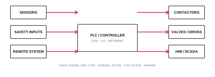
The test follows wiring, polarity, channel state, scaling and alarm interpretation end to end.
For digital inputs, check normal, active and broken-wire or de-energised states where applicable. For outputs, confirm the command, field actuation and return feedback without defeating interlocks.
For analogue loops, inject defined points across the range and record both the source value and PLC engineering value. Include under-range, over-range and sensor-fault behaviour specified by the project.
Evidence basis[1] International Electrotechnical Commission[2] International Electrotechnical Commission
Prove each signal from field condition to engineering value
The test follows wiring, polarity, channel state, scaling and alarm interpretation end to end.
Final ratings, protection, earthing, settings and interlocks follow approved project engineering.
Open full-size SVGProve logic response and remove every test override
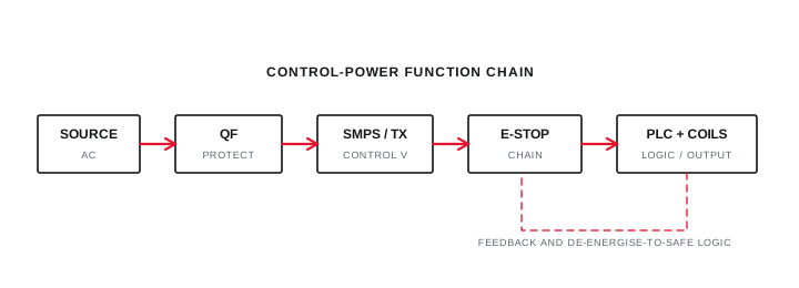
Cause-and-effect testing connects individual points to the intended process sequence and safe fallback.
Run approved scenarios for permissives, alarms, trips, start sequences and unsuccessful actions. Record preconditions and feedback rather than testing only the command path.
Maintain a live register of software forces, field links, disabled alarms and simulated devices. Handover is incomplete until each temporary condition is removed, independently checked and reflected in the final record.
Evidence basis[1] International Electrotechnical Commission[2] International Electrotechnical Commission[3] International Electrotechnical Commission
| Layer | Test | Retained evidence |
|---|---|---|
| Physical | Tag and terminal trace | Signed point sheet |
| Signal | State or injected value | Observed raw and scaled value |
| Logic | Alarm, permissive or trip | Cause-and-effect result |
| Closeout | Remove forces and links | Restoration register |
Information that makes the next review more useful.
- 01
Freeze the I/O list, tag register, cause-and-effect matrix and software revision used for testing.
- 02
Verify panel terminal, cable, field-device and PLC-channel identity before simulation.
- 03
Test digital normal, active and loss-of-signal states with feedback where provided.
- 04
Inject analogue low, midpoint, high and out-of-range values using an approved method.
- 05
Confirm engineering units, scaling, alarm thresholds, deadband and displayed precision.
- 06
Exercise permissives, interlocks and fail states without bypassing the authorised safety boundary.
- 07
Close every force, temporary link, simulation flag and punch item with restoration evidence.
Standards and technical references.
Links identify the source and scope; access to a complete standard may require purchase or organisational access.
- 01IEC 61131-2:2017 — Programmable-controller equipment requirements and testsInternational Electrotechnical Commission
- 02IEC 60364-6:2016 — Verification of low-voltage electrical installationsInternational Electrotechnical Commission
- 03IEC 61439-1:2020 — General rules for low-voltage assembliesInternational Electrotechnical Commission
Questions engineers and project teams ask.
Is seeing a PLC input change enough to close an I/O test?
No. Identity, wiring, polarity, engineering interpretation, alarms, logic use and the defined field or process response may all need evidence.
How should temporary PLC forces be controlled during commissioning?
Use an authorised live register with owner, reason and removal check, then independently verify that every force, link and simulation flag is cleared before handover.