IEEE 519 harmonic limits are applied at the user point of common coupling, so an internal panel spectrum and a PCC compliance assessment answer different questions and should not be treated as interchangeable.
- The PCC is a contractual or system interface, not simply the nearest panel to a problematic load.
- Current-distortion assessment depends on source-to-load context; a raw THD value is incomplete.
- Internal measurements explain contributors, while PCC measurements evaluate the shared interface objective.
Locate the point of common coupling first
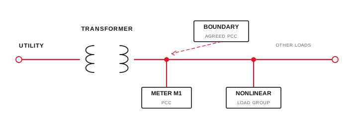
A harmonic assessment begins by identifying the interface shared with other users or the boundary defined by the supply arrangement and project agreement.
IEEE 519 describes the PCC as the interface between sources and loads and applies steady-state voltage and current distortion goals at the user PCC. In a facility with multiple transformers, generators or bus ties, more than one operating boundary may need review.
Mark the PCC and all measurement points on the current single-line diagram. If the contractual boundary is uncertain, resolve it with the relevant supply and project stakeholders before presenting a compliance conclusion.
Evidence basis[1] IEEE Standards Association[2] International Electrotechnical Commission
Locate the point of common coupling first
A harmonic assessment begins by identifying the interface shared with other users or the boundary defined by the supply arrangement and project agreement.
Final ratings, protection, earthing, settings and interlocks follow approved project engineering.
Open full-size SVGKeep THD, TDD and operating context separate
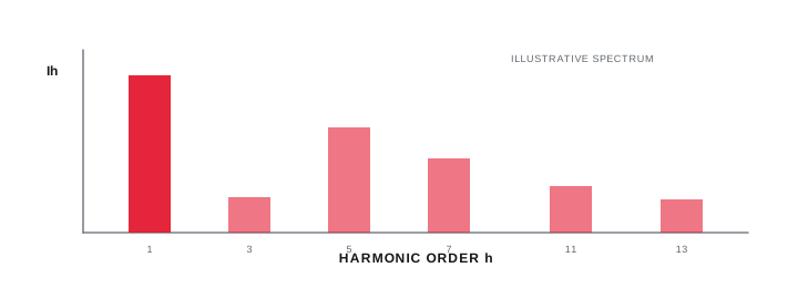
Voltage distortion, instantaneous current THD and demand-referenced current distortion describe different relationships and cannot be substituted without explanation.
Current THD can appear high at light load because its denominator is the present fundamental current. IEEE 519 current evaluation uses demand-related context at the PCC, and allowable current-distortion levels depend on the ratio of available short-circuit current to demand current.
Do not copy a limit table from memory or a secondary blog. Use the licensed current edition, the defined PCC, and the project's approved current and fault-level basis.
Evidence basis[1] IEEE Standards Association
| View | Typical boundary | Question |
|---|---|---|
| Voltage distortion | PCC or affected bus | What waveform is present at this bus? |
| Current spectrum | Load or feeder | Which orders does this load draw? |
| PCC current assessment | Defined PCC | What enters the shared interface? |
| Event trend | Synchronized locations | When and under which operating state? |
Keep THD, TDD and operating context separate
Voltage distortion, instantaneous current THD and demand-referenced current distortion describe different relationships and cannot be substituted without explanation.
Final ratings, protection, earthing, settings and interlocks follow approved project engineering.
Open full-size SVGSeparate diagnosis from acceptance evidence
Use additional internal meters to identify sources, then repeat the agreed PCC method to evaluate the system-level outcome.
A PCC trend alone may show that distortion varies but not which drive, UPS, furnace or capacitor condition contributes. Synchronized internal measurements and operating logs help trace the path and avoid assigning every harmonic observed at a bus to one device.
The mitigation acceptance plan should reuse the same PCC, instrument method, source configuration and comparable operating states. State exclusions and data gaps rather than stretching one snapshot into a facility-wide conclusion.
Evidence basis[1] IEEE Standards Association[2] International Electrotechnical Commission
Separate diagnosis from acceptance evidence
Use additional internal meters to identify sources, then repeat the agreed PCC method to evaluate the system-level outcome.

Final ratings, protection, earthing, settings and interlocks follow approved project engineering.
Open full-size SVGInformation that makes the next review more useful.
- 01
Obtain the utility or project definition of the PCC and mark it on the single-line diagram.
- 02
Record nominal voltage, transformer and source data, available fault-current information and normal source configurations.
- 03
Identify the maximum demand current basis and the observation period required by the assessment scope.
- 04
Measure voltage and current simultaneously with documented instrument class and transducers.
- 05
Log production states, capacitor steps, drives, generators and source transfers during the measurement window.
- 06
Separate PCC reporting from internal diagnostic measurements at affected buses and feeders.
- 07
Define pre- and post-mitigation measurements at the same boundary and comparable operating states.
Standards and technical references.
Links identify the source and scope; access to a complete standard may require purchase or organisational access.
Questions engineers and project teams ask.
Is every main incomer automatically the IEEE 519 PCC?
Not automatically. The PCC follows the supply and user interface defined by the system and project context. Mark and agree that boundary before applying a compliance interpretation.
Why can current THD look worse when the plant load is low?
Current THD uses the present fundamental current as its denominator, so it can rise at light load. Demand-referenced assessment and operating context are needed for a meaningful PCC evaluation.