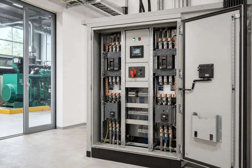
A short-circuit withstand statement must be tied to the installation fault level, protective-device behaviour, duration and the verified assembly arrangement.
- Prospective current and fault duration are both needed to define withstand duty.
- Current-limiting protection can support a conditional arrangement only when the verified conditions are preserved.
- Changes to sources, couplers, devices or bus geometry can invalidate inherited evidence.
Locate the fault boundary on the single-line
The calculated fault level must refer to the same point and operating states as the assembly specification.
Mark the assembly incomer on the latest single-line and list every source state that can energise it. Include bus couplers, parallel transformers, generator contribution and network changes only where they are legitimate operating conditions.
Record both calculation basis and date. A utility change, transformer replacement or new parallel path can alter the available fault current after the panel is installed.
Evidence basis[1] International Electrotechnical Commission[2] International Electrotechnical Commission
Locate the fault boundary on the single-line
The calculated fault level must refer to the same point and operating states as the assembly specification.

Final ratings, protection, earthing, settings and interlocks follow approved project engineering.
Open full-size SVGCoordinate withstand with protective clearing
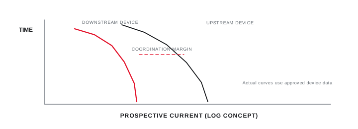
The upstream and assembly protective devices determine the current let-through and duration seen by conductors and supports.
Document device type, rating, settings and applicable current-limiting data. If the assembly rating depends on a specified upstream device or combination, state that condition explicitly in drawings and handover records.
Selectivity and withstand are related but distinct questions. A coordination study should show which objective applies at each fault level rather than assuming that a selective arrangement automatically limits energy.
Evidence basis[1] International Electrotechnical Commission[2] International Electrotechnical Commission[3] International Electrotechnical Commission
Coordinate withstand with protective clearing
The upstream and assembly protective devices determine the current let-through and duration seen by conductors and supports.
Final ratings, protection, earthing, settings and interlocks follow approved project engineering.
Open full-size SVGPreserve the verified assembly arrangement
Supports, spacing, bus geometry and device substitutions can change the conditions behind the withstand evidence.
Link the rating to the verified design, including busbar dimensions, support spacing, protective conductor arrangement and the devices used. Uncontrolled substitution can change both fault interruption and mechanical stress.
At handover, retain the fault study reference, protective settings, assembly evidence and any conditional rating in one traceable record.
Evidence basis[1] International Electrotechnical Commission[2] International Electrotechnical Commission[3] International Electrotechnical Commission
Information that makes the next review more useful.
- 01
Provide maximum and relevant minimum prospective fault current at the assembly connection point.
- 02
Identify source transformers, generators, couplers and parallel states included in the calculation.
- 03
Record fault duration or protective-device clearing behaviour for the evaluated condition.
- 04
Define busbar, support, protective conductor and incoming or outgoing connection arrangements.
- 05
Provide protective-device type, settings, current-limiting information and selectivity objective.
- 06
Identify the assembly verification route and any conditional device coordination.
- 07
Retain calculation assumptions and the exact built configuration with the final rating evidence.
Standards and technical references.
Links identify the source and scope; access to a complete standard may require purchase or organisational access.
Questions engineers and project teams ask.
Is prospective fault current alone enough to specify panel withstand?
No. The relevant duration, protective-device behaviour, source topology, assembly arrangement and verification conditions are also part of the duty statement.
Can an upstream circuit-breaker support a conditional short-circuit rating?
It can only do so where the assembly and device combination are supported by applicable verification evidence and the exact protective conditions are preserved in service.