

An IP code describes defined enclosure protection tests; it does not replace a complete review of heat, corrosion, condensation, installation and maintenance access.
- An IP designation covers defined access and ingress conditions, not every environmental hazard.
- Cable entries and ventilation components are part of the final enclosure protection boundary.
- Increasing sealing can worsen temperature and condensation unless the complete heat path is reviewed.
Describe the exposure before choosing the code
A factual exposure brief prevents an enclosure rating from becoming an unsupported shorthand for the whole environment.
Record the source and direction of dust or water, cleaning method, frequency, shelter, nearby process contamination and likely access. Distinguish occasional splash from washdown and settled dust from continuously airborne conductive contamination.
Add temperature, humidity, condensation, solar and corrosive exposure. IEC 60529 addresses the IP classification system, while other hazards and performance requirements need their own design evidence.
Evidence basis[1] International Electrotechnical Commission[2] International Electrotechnical Commission
Describe the exposure before choosing the code
A factual exposure brief prevents an enclosure rating from becoming an unsupported shorthand for the whole environment.

Final ratings, protection, earthing, settings and interlocks follow approved project engineering.
Open full-size SVGProtect every opening in the assembled condition
Doors, glands, vents, operator devices and field modifications can change the boundary established by the bare enclosure.
List every penetration and the component used to maintain the intended protection. Include cable diameter range, blanking of spare holes, door hardware, viewing windows and any pressure-equalisation or drainage device.
Installation workmanship and later maintenance matter. An enclosure label cannot compensate for an unsealed gland plate, damaged gasket or field cut-out without suitable evidence.
Evidence basis[1] International Electrotechnical Commission[2] International Electrotechnical Commission
Protect every opening in the assembled condition
Doors, glands, vents, operator devices and field modifications can change the boundary established by the bare enclosure.
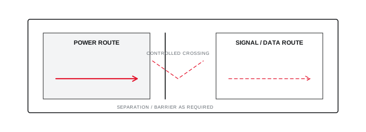
Final ratings, protection, earthing, settings and interlocks follow approved project engineering.
Open full-size SVGBalance ingress control with heat and condensation
A more sealed enclosure changes ventilation, internal temperature and moisture behaviour.
Calculate or verify the internal thermal condition with the chosen filters, fans, heat exchangers or sealed cooling method. Define blocked-filter and fan-failure considerations where those devices are essential to acceptable temperature.
For condensation risk, document the operating and idle cycle, internal heat, ambient swings and any anti-condensation strategy. Retain maintenance actions required to preserve both cooling and ingress protection.
Evidence basis[1] International Electrotechnical Commission[2] International Electrotechnical Commission[3] International Electrotechnical Commission
Information that makes the next review more useful.
- 01
Describe indoor or outdoor location, shelter, washdown, dust source, contamination and corrosion exposure.
- 02
Define access, contact and ingress objectives without guessing an IP code from the room name.
- 03
Record ambient range, solar exposure, altitude, humidity and condensation risk.
- 04
Map cable entries, doors, gland plates, ventilation devices, windows and operator interfaces.
- 05
Review heat dissipation against any filtered, fan-assisted or sealed enclosure strategy.
- 06
Define inspection and maintenance access that preserves the intended enclosure boundary.
- 07
Retain test, component and installation evidence for the complete assembled condition.
Standards and technical references.
Links identify the source and scope; access to a complete standard may require purchase or organisational access.
- 01IEC 60529 consolidated edition — Degrees of protection provided by enclosuresInternational Electrotechnical Commission
- 02IEC 61439-2:2020 — Power switchgear and controlgear assembliesInternational Electrotechnical Commission
- 03IEC TR 60890:2022 — Temperature-rise calculation inside assembliesInternational Electrotechnical Commission
Questions engineers and project teams ask.
Does a higher IP number always make an electrical panel safer?
No. The required protection must match the exposure, and increased sealing can create thermal, condensation, maintenance or pressure-related problems if the assembly is not reviewed as a whole.
Do cable glands affect the final panel IP protection?
Yes. Glands, spare-hole blanking, cut-outs, doors, vents and installed devices are part of the assembled enclosure boundary and need compatible evidence and workmanship.




