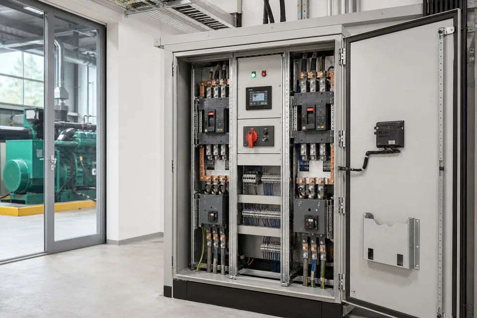
A control-panel FAT should trace approved requirements to observable checks, results, instruments, witnesses and exceptions; it is not a substitute for every site or high-power test.
- Every FAT step should point to an approved requirement and a visible acceptance criterion.
- Design verification, routine verification and project functional testing are related but not interchangeable.
- Record exceptions and untested site dependencies instead of converting them into silent assumptions.
Freeze the approved test basis
A FAT is reproducible only when the drawing, BOM, software, settings and requirement revisions under test are identified.
Create a cover sheet listing the panel identity and the approved document revisions. If software or settings are part of the scope, record the version or checksum and retain the tested export according to the project document process.
Map each required function to a test step and acceptance statement. Avoid vague entries such as 'checked OK' where the actual observation, state transition or measured value can be recorded.
Evidence basis[1] International Electrotechnical Commission[2] International Electrotechnical Commission
Freeze the approved test basis
A FAT is reproducible only when the drawing, BOM, software, settings and requirement revisions under test are identified.
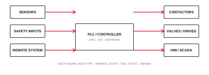
Final ratings, protection, earthing, settings and interlocks follow approved project engineering.
Open full-size SVGSeparate inspection, routine verification and simulation
Visual and mechanical inspection, assembly routine checks and low-energy functional simulation each prove a different part of the delivered requirement.
Inspection can confirm component identity, labels, workmanship, access and drawing agreement. Routine verification under the applicable assembly standard covers defined construction and performance checks for the completed assembly. Functional simulation checks sequences, interlocks, alarms and I/O using an approved safe arrangement.
State which tests cannot be reproduced at the factory, including actual fault level, full site load, field-device dynamics, network interfaces or process permissives. Assign those items to commissioning or site acceptance.
Evidence basis[1] International Electrotechnical Commission[2] International Electrotechnical Commission[3] International Electrotechnical Commission
| Evidence group | Example | Does not prove |
|---|---|---|
| Visual inspection | Labels and component identity | Electrical performance under load |
| Routine verification | Wiring and dielectric checks | Every site operating state |
| Functional simulation | Interlocks and alarms | Actual process dynamics |
| Document review | Drawing and BOM revision | Physical installation condition |
Separate inspection, routine verification and simulation
Visual and mechanical inspection, assembly routine checks and low-energy functional simulation each prove a different part of the delivered requirement.
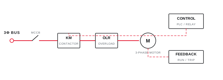
Final ratings, protection, earthing, settings and interlocks follow approved project engineering.
Open full-size SVGControl exceptions and handover evidence
Punch items, concessions and deferred site tests need owners, due states and closure evidence before they become part of the delivered record.
Record every deviation with its requirement reference, observed condition, risk or impact, responsible party and agreed disposition. Photographs can support a record but should not replace measured or functional evidence where that is the acceptance basis.
The final pack can include the signed test plan, results, instrument list, punch closure, tested settings, as-built drawings and a list of site tests still required. Keep the status of each item explicit.
Evidence basis[1] International Electrotechnical Commission[2] International Electrotechnical Commission
Information that makes the next review more useful.
- 01
Freeze the approved drawing, BOM, I/O, cause-and-effect and settings revisions used for the test.
- 02
Create a requirement-to-test matrix with method, acceptance criterion and evidence record.
- 03
Identify design-verification evidence and routine checks applicable to the assembly.
- 04
List instruments, calibration status, simulated signals, temporary supplies and safety controls.
- 05
Define visual, mechanical, wiring, continuity, insulation and functional sequence checks.
- 06
Assign witness, review and hold points with authority for accepting or recording exceptions.
- 07
Close punch items through an evidence-linked record before release or approved concession.
Standards and technical references.
Links identify the source and scope; access to a complete standard may require purchase or organisational access.
- 01IEC 61439-1:2020 — General rules for low-voltage assembliesInternational Electrotechnical Commission
- 02IEC 61439-2:2020 — Power switchgear and controlgear assembliesInternational Electrotechnical Commission
- 03IEC 60204-1:2016 — Electrical equipment of machinesInternational Electrotechnical Commission
Questions engineers and project teams ask.
Does a factory acceptance test replace site commissioning?
No. FAT can verify assembly and simulated functions before shipment, while site commissioning confirms installation interfaces, field devices, actual sources, loads and process conditions.
What should happen when a FAT step fails?
Record the requirement, observation, owner and agreed disposition. Retest after correction or document an authorised concession; do not erase the failed observation from the evidence trail.