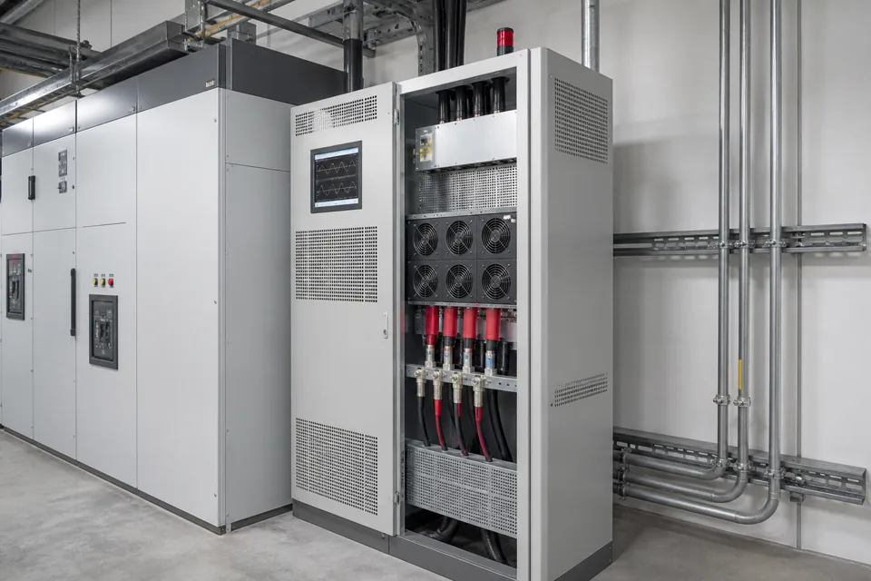
Neutral-current assessment separates ordinary phase imbalance from zero-sequence harmonic components that can add in a four-wire distribution system.
- Triplen harmonic components can add in the neutral even when phase RMS currents look balanced.
- Simultaneous phase and neutral spectra are more diagnostic than isolated clamp readings.
- Neutral adequacy depends on topology, wiring method, thermal conditions and the actual current composition.
Trace the complete neutral and source path
Transformer connection, shared circuits and switching devices define where zero-sequence current can flow.
Mark every neutral conductor, link, busbar, switched pole and parallel path from the load groups to the source. Confirm whether circuits share a neutral and whether any changeover arrangement changes the neutral reference.
The assessment should not infer topology from cable colours or panel labels. Use verified drawings and field tracing under an authorised procedure.
Evidence basis[1] International Electrotechnical Commission[2] International Electrotechnical Commission
Trace the complete neutral and source path
Transformer connection, shared circuits and switching devices define where zero-sequence current can flow.

Final ratings, protection, earthing, settings and interlocks follow approved project engineering.
Open full-size SVGSeparate imbalance from triplen harmonic current
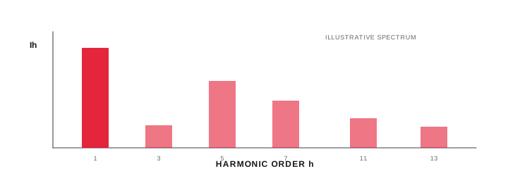
Simultaneous spectra distinguish fundamental residual current from harmonic components that add in the neutral.
Measure phase and neutral RMS current at the same time, then inspect the fundamental and individual harmonic orders. Correlate results with lighting, IT, UPS and other single-phase electronic load states.
IEC 60364-5-52 addresses wiring-system selection and includes harmonic-current considerations. The measurement plan still needs an appropriate instrument, bandwidth and declared aggregation method.
Evidence basis[1] International Electrotechnical Commission[3] International Electrotechnical Commission
Separate imbalance from triplen harmonic current
Simultaneous spectra distinguish fundamental residual current from harmonic components that add in the neutral.
Final ratings, protection, earthing, settings and interlocks follow approved project engineering.
Open full-size SVGReview conductor, joint and enclosure heating
Current magnitude becomes meaningful only with conductor and installation data plus observed thermal condition.
Record conductor cross-section, material, grouping, enclosure temperature and terminal rating. Inspect neutral bars, links and joints, since a local resistance defect can overheat at a current that the conductor itself could otherwise carry.
Any resizing, reconfiguration or protection decision requires the applicable design calculation. Do not use a generic full-size-neutral rule as a substitute for the measured spectrum and installed wiring method.
Evidence basis[1] International Electrotechnical Commission[2] International Electrotechnical Commission[3] International Electrotechnical Commission
| Input | What it distinguishes | Action |
|---|---|---|
| Fundamental current | Phase imbalance | Balance and load review |
| Triplen spectrum | Zero-sequence harmonic addition | Harmonic design review |
| Thermal inspection | Local resistance or overload | Joint and conductor assessment |
| Wiring method | Permitted conductor duty | Documented calculation |
Information that makes the next review more useful.
- 01
Confirm the transformer winding, earthing arrangement and complete four-wire single-line path.
- 02
Identify shared neutrals, reduced neutrals, parallel conductors and any neutral switching devices.
- 03
Measure all phase and neutral currents simultaneously through representative load states.
- 04
Retain fundamental and harmonic components rather than relying on total RMS current alone.
- 05
Record conductor material, cross-section, installation method, grouping and termination temperature limits.
- 06
Inspect neutral joints, busbars and terminations for condition and thermal evidence.
- 07
Route conductor adequacy and protection changes through a competent design review.
Standards and technical references.
Links identify the source and scope; access to a complete standard may require purchase or organisational access.
- 01IEC 60364-5-52:2009+AMD1:2024 — Selection and erection of wiring systemsInternational Electrotechnical Commission
- 02IEC 60364-5-54:2011+AMD1:2021 — Earthing arrangements and protective conductorsInternational Electrotechnical Commission
- 03IEC 61000-4-30:2025 — Power-quality measurement methodsInternational Electrotechnical Commission
Questions engineers and project teams ask.
Can balanced phase RMS currents still produce high neutral current?
Yes. Triplen harmonic components from single-phase nonlinear loads can be phase-aligned and add in the neutral even when the fundamental phase loading appears balanced.
Does neutral current alone prove the conductor is undersized?
No. The spectrum, duration, wiring method, conductor data, ambient condition, terminations and applicable calculation are needed before judging adequacy.