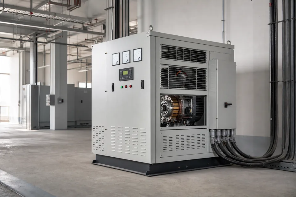
Motor starting is a dynamic event: current magnitude, acceleration time, source strength and load torque together shape the voltage dip seen across the plant.
- Starting current and acceleration time both affect the depth and duration of voltage dip.
- The same motor can behave differently on utility and generator sources.
- Acceptance should include the response of sensitive plant equipment, not only whether the motor reaches speed.
Describe the motor and driven-load start
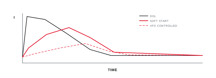
Starting performance depends on the motor characteristic, starter method and torque needed to accelerate the load.
Record rated data, locked-rotor or manufacturer starting information, inertia and the actual mechanical starting condition. A pump starting against a particular system state can demand a different acceleration profile from an unloaded commissioning run.
IEC 60034-12 defines starting-performance parameters for relevant cage induction motor designs. Use project and manufacturer data for the installed machine rather than assuming one multiple of full-load current.
Evidence basis[1] International Electrotechnical Commission[2] International Electrotechnical Commission
Describe the motor and driven-load start
Starting performance depends on the motor characteristic, starter method and torque needed to accelerate the load.
Final ratings, protection, earthing, settings and interlocks follow approved project engineering.
Open full-size SVGModel every source state that matters
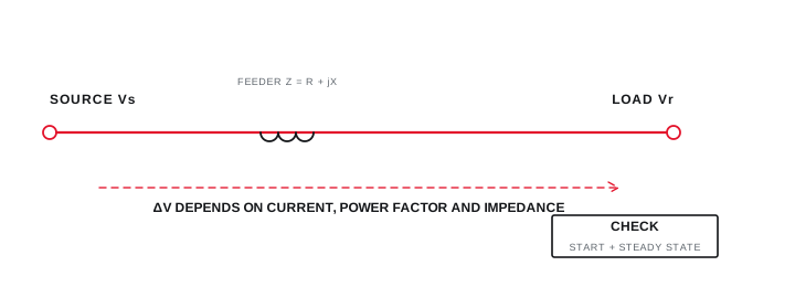
Transformer, generator and cable impedance shape the bus response to the same starting current.
Build the path from source to motor and identify the bus where sensitive equipment is connected. Include generator subtransient data and control behaviour when generator operation is a legitimate state.
Simultaneous loads and automatic capacitor or voltage-control actions can change the observed event. Record them rather than forcing the waveform into a single-source explanation.
Evidence basis[1] International Electrotechnical Commission[2] International Electrotechnical Commission
Model every source state that matters
Transformer, generator and cable impedance shape the bus response to the same starting current.
Final ratings, protection, earthing, settings and interlocks follow approved project engineering.
Open full-size SVGMeasure the event and decide against plant impact
Time-synchronised voltage and current traces connect the starting sequence to equipment behaviour.
Capture RMS trends with sufficient time resolution for the event and note contactor, soft-starter or drive transitions. Where possible, measure at both the motor supply and the affected upstream bus.
Compare options such as source strengthening, sequence changes, soft starting or a drive against acceleration, process and network requirements. Verify the chosen change using the same documented start condition.
Evidence basis[1] International Electrotechnical Commission[2] International Electrotechnical Commission
Measure the event and decide against plant impact
Time-synchronised voltage and current traces connect the starting sequence to equipment behaviour.

Final ratings, protection, earthing, settings and interlocks follow approved project engineering.
Open full-size SVGInformation that makes the next review more useful.
- 01
Capture motor nameplate, starting-performance data, inertia and driven-load starting requirement.
- 02
Identify direct-on-line, star-delta, soft-starter or drive method and its actual settings.
- 03
Provide transformer, generator, cable and source short-circuit information for each operating state.
- 04
List contactors, controls, drives and processes that are sensitive to a temporary voltage reduction.
- 05
Record time-synchronised voltage, current and start duration at the source and affected bus where possible.
- 06
Compare measured behaviour with an explicit operational acceptance objective.
- 07
Verify the selected change under the same defined starting condition.
Standards and technical references.
Links identify the source and scope; access to a complete standard may require purchase or organisational access.
Questions engineers and project teams ask.
Can motor kW alone predict the starting voltage dip?
No. Starting-current profile, acceleration time, source and cable impedance, starter method, load torque and the active network configuration all affect the event.
Why can a motor start correctly on utility but disturb a generator supply?
A generator source often has different impedance and voltage-regulator dynamics, so the same starting current can create a deeper or longer voltage response.