

Motor protection settings should reconcile the motor thermal duty and starting profile with feeder conductors, starter capability, fault protection and process operation.
- Motor full-load current does not define every overload and short-circuit setting.
- The actual starting profile must fit inside the intended thermal and protection response.
- Coordination evidence applies to the specific combination and fault conditions declared by the manufacturer.
Assemble the complete motor-feeder record
Motor, starter, cable, protection and fault-level data belong in one settings input sheet.
Record motor rating and current, duty, starting method, starter or drive, overload device, short-circuit protective device and cable path. Include ambient and enclosure conditions that affect equipment or conductor duty.
IEC 60947-4-1 addresses contactors and motor-starters within its scope. IEC 60947-2 addresses circuit-breakers; final coordination relies on the applicable product data and declared combination.
Evidence basis[1] International Electrotechnical Commission[2] International Electrotechnical Commission
Assemble the complete motor-feeder record
Motor, starter, cable, protection and fault-level data belong in one settings input sheet.
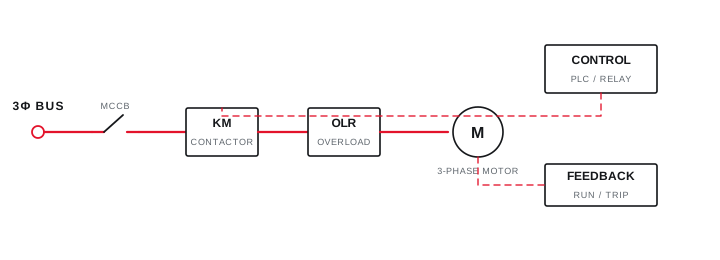
Final ratings, protection, earthing, settings and interlocks follow approved project engineering.
Open full-size SVGFit the starting profile inside the protection boundary
Current magnitude and acceleration time should be assessed together for the actual driven load.
Use a measured trace or a study that includes source voltage, starter method, motor characteristics and load torque. Record cold and hot restart expectations plus the permitted number of starts.
IEC 60034-12 addresses starting performance for motors within its scope. Project settings still depend on the selected motor, driven machine and protection-device characteristic.
Evidence basis[1] International Electrotechnical Commission[3] International Electrotechnical Commission
Fit the starting profile inside the protection boundary
Current magnitude and acceleration time should be assessed together for the actual driven load.
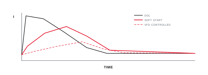
Final ratings, protection, earthing, settings and interlocks follow approved project engineering.
Open full-size SVGCommission settings against measured behaviour
Final records should show installed settings, representative starts and the response of alarms and trips.
Verify CT ratios, phase mapping, thermal memory, reset mode, trip class or curve, ground-fault functions and communication mapping as applicable. Do not create a trip test that places the process or motor at unmanaged risk.
Retain final settings, device identity, test method, current traces and any protection functions not exercised. A successful start alone does not prove the full fault-protection chain.
Evidence basis[1] International Electrotechnical Commission[2] International Electrotechnical Commission[3] International Electrotechnical Commission
| Input | Constrains | Evidence |
|---|---|---|
| Starting trace | Overload response | Current and time |
| Cable data | Thermal protection | Installed wiring method |
| Fault level | Short-circuit duty | Study at feeder |
| Process duty | Restart and stall logic | Operating narrative |
Information that makes the next review more useful.
- 01
Collect motor nameplate, datasheet, efficiency, service factor where applicable and thermal information.
- 02
Record starter type, utilisation category, overload device model and short-circuit protective device.
- 03
Obtain measured or calculated starting current and acceleration time for the driven load.
- 04
Confirm cable material, cross-section, installation method, length and permitted duty.
- 05
Record prospective fault level and the declared starter-protection coordination data.
- 06
Define process restart, stall, jam, phase-loss and unsuccessful-start requirements.
- 07
Commission with retained current traces, trip tests and final setting exports where supported.
Standards and technical references.
Links identify the source and scope; access to a complete standard may require purchase or organisational access.
- 01IEC 60947-4-1:2023 — Electromechanical contactors and motor-startersInternational Electrotechnical Commission
- 02IEC 60947-2:2024 — Low-voltage circuit-breakersInternational Electrotechnical Commission
- 03IEC 60034-12:2024 — Starting performance of single-speed three-phase cage motorsInternational Electrotechnical Commission
Questions engineers and project teams ask.
Should a motor overload relay always be set exactly to nameplate current?
Not automatically. Motor data, device instructions, duty, ambient conditions, starting profile and the project protection philosophy must be reconciled by the responsible designer.
Does one successful motor start prove the feeder protection is correct?
No. It confirms one operating event, while thermal overload, phase loss, stall, short-circuit coordination and fault response need their own evidence or declared limitations.




