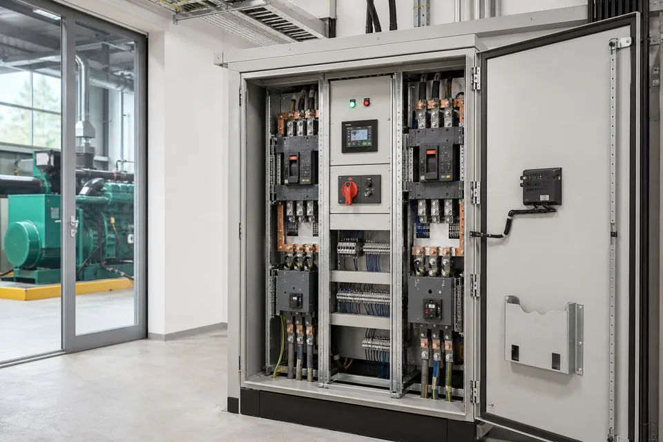
Low-voltage panel layout is a coordinated decision between safety, temperature rise, service conditions, cable routing and maintenance access; internal separation alone does not solve every objective.
- Internal separation is selected for an operational and safety objective, not as a prestige label.
- Temperature-rise verification belongs to the complete loaded assembly and service condition.
- Ingress protection, cooling and maintainability must be checked together.
Organise the panel into functional zones
Incoming, power conversion, control, terminal and communication functions need defined boundaries and safe installation and maintenance access.
Begin with the functional single-line and I/O architecture, then assign physical zones for the incomer, bus system, feeders, drives, control power, PLC, relays, terminals and cable entry. Keep heat, electromagnetic compatibility, creepage, clearance and wiring access visible throughout the layout review.
A compact panel is not automatically an efficient panel. Space needed for conductor bending, tightening tools, ventilation, replacement and safe inspection is part of the engineering requirement.
Evidence basis[1] International Electrotechnical Commission[2] International Electrotechnical Commission
Organise the panel into functional zones
Incoming, power conversion, control, terminal and communication functions need defined boundaries and safe installation and maintenance access.

Final ratings, protection, earthing, settings and interlocks follow approved project engineering.
Open full-size SVGSelect separation and cable routing deliberately
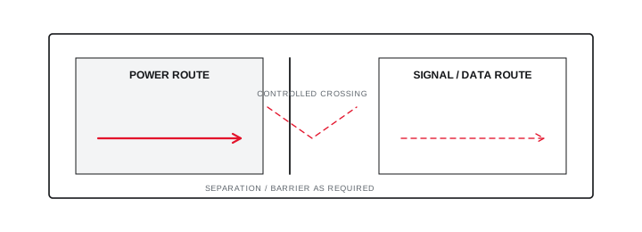
Barriers and routes should support the agreed isolation, maintenance and interference objectives without creating inaccessible or thermally trapped compartments.
IEC 61439-2 addresses forms of internal separation for power switchgear and controlgear assemblies. The chosen form should follow the project's access and continuity needs, the parts that may remain live, and the assembly design verified by its original manufacturer.
Separate high-current and sensitive signal paths where required, use controlled crossings, and document shield and earth termination. Do not treat one minimum distance as universal across voltage, cable type, enclosure and EMC environment.
Evidence basis[1] International Electrotechnical Commission[2] International Electrotechnical Commission[3] International Electrotechnical Commission
Select separation and cable routing deliberately
Barriers and routes should support the agreed isolation, maintenance and interference objectives without creating inaccessible or thermally trapped compartments.
Final ratings, protection, earthing, settings and interlocks follow approved project engineering.
Open full-size SVGVerify heat rejection in the stated environment
Device losses, diversity, enclosure construction, cooling and ambient conditions determine internal temperature and component duty.
Collect manufacturer loss data, expected current and diversity for every significant source. Check natural convection paths, fan and filter duty, air recirculation, hot spots near reactors or drives and the consequence of a stopped fan or blocked filter.
Temperature-rise verification under IEC 61439 is not replaced by a room-temperature visual inspection. Define the accepted verification route and the service conditions it represents, including active cooling where used.
Evidence basis[1] International Electrotechnical Commission[2] International Electrotechnical Commission
| Condition | Possible effect | Required evidence |
|---|---|---|
| High ambient | Reduced component thermal margin | Rated data and verification |
| Dust or moisture | Ingress and cooling conflict | Enclosure and maintenance plan |
| Drive or reactor losses | Local hot spots | Loss map and airflow review |
| Restricted access | Maintenance and termination risk | Layout and access dimensions |
Information that makes the next review more useful.
- 01
State indoor or outdoor location, ambient range, altitude, dust, moisture, corrosive agents and solar exposure.
- 02
List circuit currents, diversity, device losses, drives, reactors, transformers and other internal heat sources.
- 03
Define required internal separation and the operational reason for it.
- 04
Map power, control, communication and field cable entry with bending and termination space.
- 05
Identify doors, covers and parts that can remain live during maintenance states.
- 06
Define cooling method, filter maintenance, fan failure and blocked-air-path response.
- 07
Agree design and routine verification evidence for the complete assembly.
Standards and technical references.
Links identify the source and scope; access to a complete standard may require purchase or organisational access.
- 01IEC 61439-1:2020 — General rules for low-voltage assembliesInternational Electrotechnical Commission
- 02IEC 61439-2:2020 — Power switchgear and controlgear assembliesInternational Electrotechnical Commission
- 03IEC 60204-1:2016 — Electrical equipment of machinesInternational Electrotechnical Commission
Questions engineers and project teams ask.
Does a higher form of panel separation always mean a better panel?
No. Separation should match the safety, access and continuity objective. It can add space, cost and thermal constraints, so it must be selected and verified as part of the complete assembly.
Can an enclosure fan alone prove the panel will stay within temperature limits?
No. The complete loss, airflow, ambient, filter, failure-state and assembly verification method must be considered. A fan rating without system context is incomplete evidence.