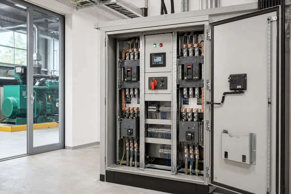
Busbar sizing is an assembly decision shaped by current, material, enclosure, arrangement, joints, heat sources, ventilation and the selected verification route.
- Busbar ampacity cannot be separated from enclosure and assembly heat flow.
- Joints, supports and nearby devices can govern local temperature even when conductor area looks adequate.
- The verification method and its limits belong in the design record.
Define the bus section duty and operating states
Current, diversity, neutral duty and alternate configurations determine which thermal cases deserve verification.
Separate incomer, coupler, horizontal bus, vertical distribution and outgoing connection duties. Include normal, alternate-source, parallel or reduced-ventilation states only where they are part of the approved operating philosophy.
Harmonic-rich single-phase loading can change neutral and loss assumptions. Record the expected load spectrum or state that it is unknown rather than embedding an optimistic balance assumption.
Evidence basis[1] International Electrotechnical Commission[2] International Electrotechnical Commission
Define the bus section duty and operating states
Current, diversity, neutral duty and alternate configurations determine which thermal cases deserve verification.
Final ratings, protection, earthing, settings and interlocks follow approved project engineering.
Open full-size SVGModel the conductor and enclosure heat path
The assembly transfers losses through air movement, metalwork, joints and surfaces, not through copper area alone.
Document enclosure size, compartments, internal obstructions, device losses, cable entry congestion, ventilation openings and the intended installation environment. Joint overlap, preparation and accessible tightening method also affect local behaviour.
IEC TR 60890 provides a calculation method within its stated scope, while IEC 61439 defines the assembly verification context. Use a route that fits the actual design and retain where interpolation, comparison or assumptions were used.
Evidence basis[1] International Electrotechnical Commission[2] International Electrotechnical Commission[3] International Electrotechnical Commission
Model the conductor and enclosure heat path
The assembly transfers losses through air movement, metalwork, joints and surfaces, not through copper area alone.

Final ratings, protection, earthing, settings and interlocks follow approved project engineering.
Open full-size SVGVerify the result and retain its boundaries
A temperature result is useful only when the loading, ambient and measurement locations are traceable.
Record test or calculation conditions, current distribution, ambient reference, stabilisation criterion and measurement points. Local joints and device terminals may require attention beyond a headline enclosure temperature.
If the final build changes enclosure size, ventilation, device arrangement or bus geometry, reassess whether the earlier evidence still applies.
Evidence basis[1] International Electrotechnical Commission[2] International Electrotechnical Commission[3] International Electrotechnical Commission
| Input | Design effect | Record |
|---|---|---|
| Current by bus section | Sets losses by operating state | Load and diversity schedule |
| Enclosure and partitions | Shapes internal air movement | Assembly layout |
| Joints and devices | Create local heat sources | Connection schedule |
| Ambient and ventilation | Sets heat-rejection boundary | Installation assumptions |
Information that makes the next review more useful.
- 01
Provide rated and design currents for each bus section, including diversity and operating states.
- 02
Record conductor material, dimensions, surface treatment, joint arrangement and support geometry.
- 03
Map adjacent devices, cable entries and internal heat sources around the busbar path.
- 04
Define ambient, installation location, enclosure dimensions, partitions and ventilation condition.
- 05
Identify neutral loading, harmonic context and any sustained unbalance that changes conductor duty.
- 06
Select the applicable assembly verification route before relying on calculation or comparison.
- 07
Retain assumptions and temperature-rise evidence with the final assembly design.
Standards and technical references.
Links identify the source and scope; access to a complete standard may require purchase or organisational access.
- 01IEC 61439-1:2020 — General rules for low-voltage assembliesInternational Electrotechnical Commission
- 02IEC 61439-2:2020 — Power switchgear and controlgear assembliesInternational Electrotechnical Commission
- 03IEC TR 60890:2022 — Temperature-rise calculation inside assembliesInternational Electrotechnical Commission
Questions engineers and project teams ask.
Can LV busbars be sized from a single current-density rule?
A shortcut may support an early estimate, but the final assembly decision must include enclosure, arrangement, joints, heat sources, ambient and the chosen verification route.
When should a busbar temperature-rise assessment be revisited?
Revisit it when current duty, enclosure, ventilation, partitions, device losses, bus geometry, joint arrangement or installation ambient changes beyond the evidence basis.