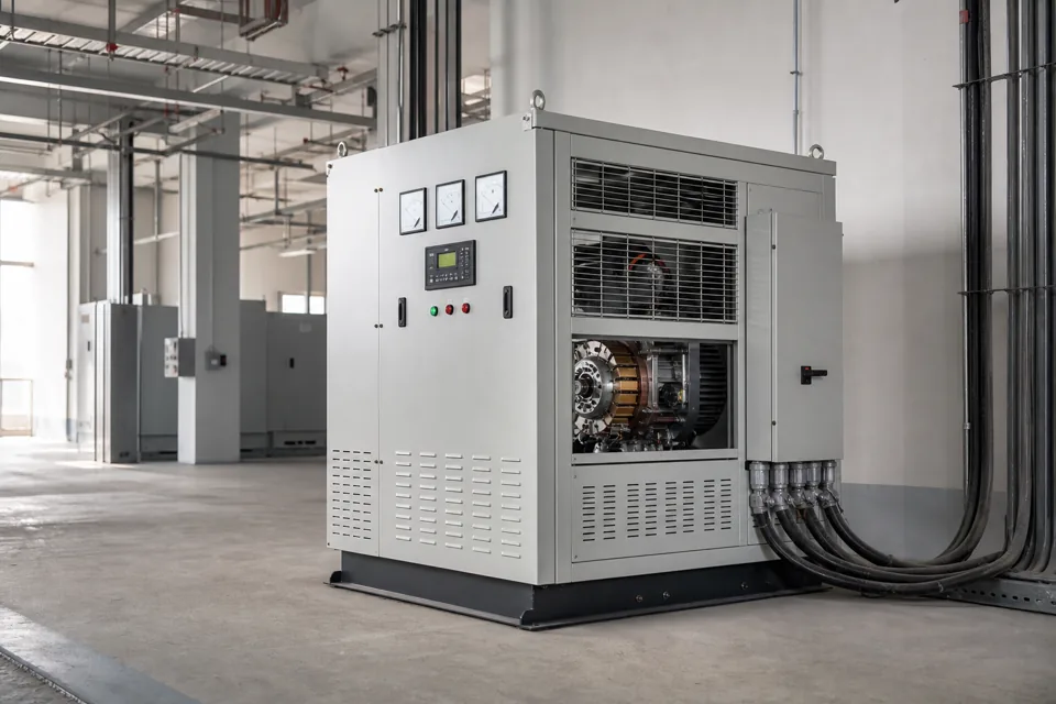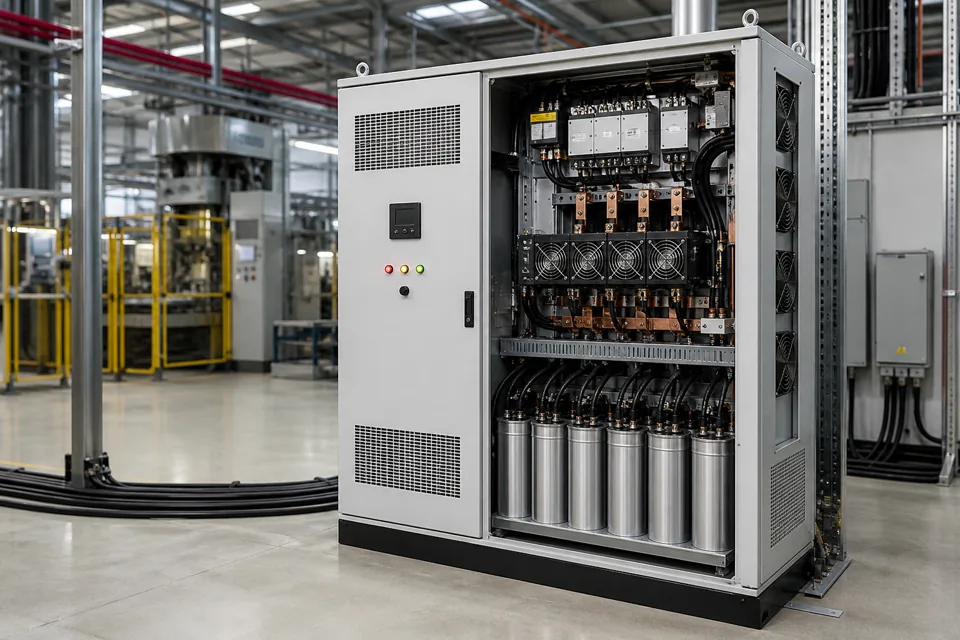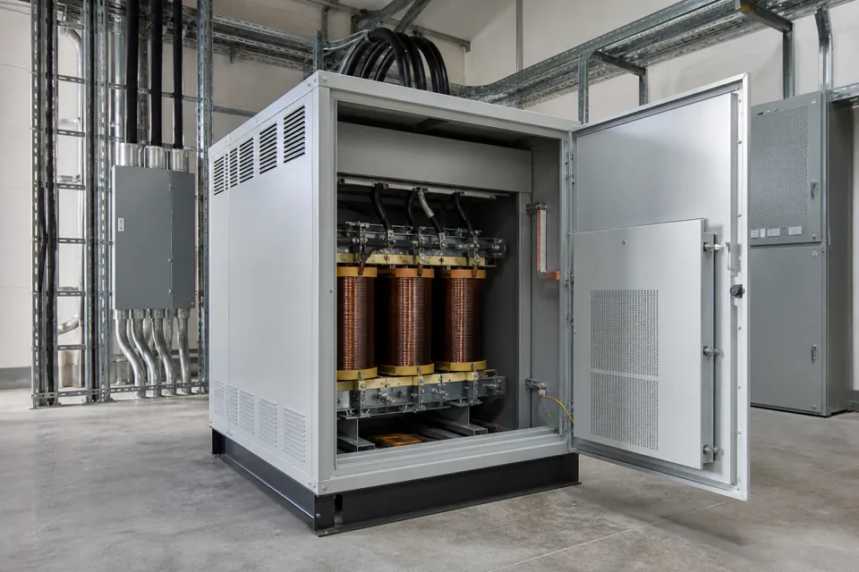
An isolation transformer provides galvanic separation between windings, while its useful application still depends on system earthing, load behaviour, shielding and protection.
- Galvanic isolation separates windings but does not automatically regulate voltage or remove all harmonics.
- Secondary earthing and protection must be deliberately designed for the new separately derived circuit where applicable.
- Non-linear loads can increase RMS and thermal duty beyond what fundamental-frequency kW suggests.
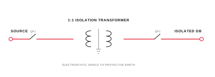
- An electrostatic shield addresses a defined capacitive coupling path and needs an appropriate protective-earth connection.
Define the required isolation boundary
State which circuits must be galvanically separated and which disturbance or safety objective the transformer supports.
Separate primary and secondary windings interrupt a direct conductive path while transferring energy magnetically. This can support a separately defined secondary system and reduce selected common-mode coupling when the construction and earthing arrangement are appropriate.
Isolation does not create an uninterruptible source, compensate sustained voltage variation or cancel load-generated harmonic current by itself. Those objectives require separate functions or a combined engineered system.
Define the required isolation boundary
State which circuits must be galvanically separated and which disturbance or safety objective the transformer supports.
Final ratings, protection, earthing, settings and interlocks follow approved project engineering.
Open full-size SVGRate for continuous, inrush and non-linear duty
Transformer kVA must cover the actual simultaneous load and its current waveform, starting and environmental conditions.
Build a load schedule with continuous demand, starting or energisation inrush, cyclic overload and future allowance. UPS inputs, rectifiers and other non-linear loads can have current waveforms that increase winding and core heating.
Specify ambient, enclosure, ventilation, altitude, permissible temperature rise, insulation system and acoustic constraints. Protection on both sides should coordinate with transformer inrush and fault behaviour.
Rate for continuous, inrush and non-linear duty
Transformer kVA must cover the actual simultaneous load and its current waveform, starting and environmental conditions.
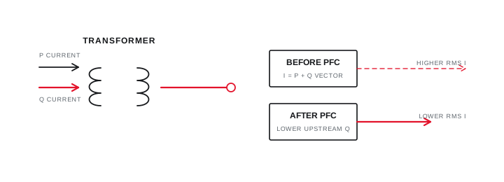
Final ratings, protection, earthing, settings and interlocks follow approved project engineering.
Open full-size SVGCoordinate shield, earthing and secondary protection
The shield and secondary reference arrangement must follow the electrical safety architecture and intended common-mode path.
An electrostatic shield between windings is normally connected to protective earth according to the approved design so capacitively coupled noise has a defined path. Shield wiring, enclosure bonding and conductor routing affect practical performance.
Determine whether and where the secondary is referenced to earth, how protective devices operate and which exposed conductive parts are bonded. Do not leave these decisions to site improvisation after the transformer is delivered.
Coordinate shield, earthing and secondary protection
The shield and secondary reference arrangement must follow the electrical safety architecture and intended common-mode path.
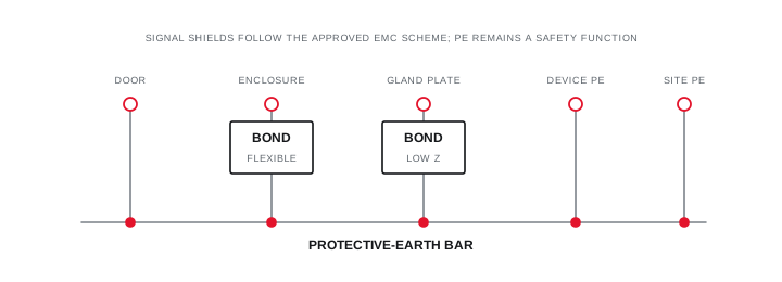
Final ratings, protection, earthing, settings and interlocks follow approved project engineering.
Open full-size SVGInformation that makes the next review more useful.
- 01
Primary and secondary voltage, frequency, phases and required connection.
- 02
Continuous kVA, diversity, inrush, crest factor and overload duty.
- 03
Source and secondary earthing and protection philosophy.
- 04
Electrostatic shield, common-mode attenuation or special insulation objective.
- 05
Non-linear load spectrum and acceptable temperature rise or derating basis.
- 06
Indoor or outdoor environment, enclosure, ventilation, noise and access.
Standards and technical references.
Links identify the source and scope; access to a complete standard may require purchase or organisational access.
- 01IEC 61558-1:2017 — Safety of transformers, reactors and power-supply unitsInternational Electrotechnical Commission
- 02Central Electricity Authority safety and electric-supply regulations, 2023Central Electricity Authority, Government of India
- 03IEC 61000-4-30:2025 — Power-quality measurement methodsInternational Electrotechnical Commission
Questions engineers and project teams ask.
Does an isolation transformer stabilise output voltage?
A conventional fixed-ratio isolation transformer follows input voltage within its regulation characteristics. Sustained voltage correction requires a stabilising or regulated function selected for the measured condition.
Is an electrostatic shield the same as protective isolation?
No. The shield addresses capacitive coupling between windings, while protective separation and insulation depend on the complete transformer construction, applicable requirements and installation.