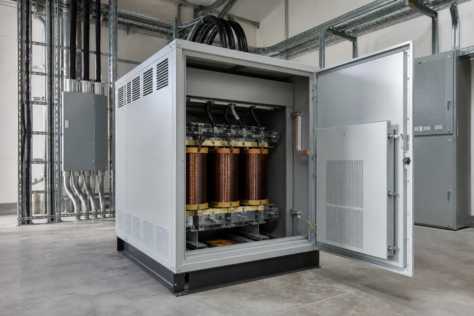
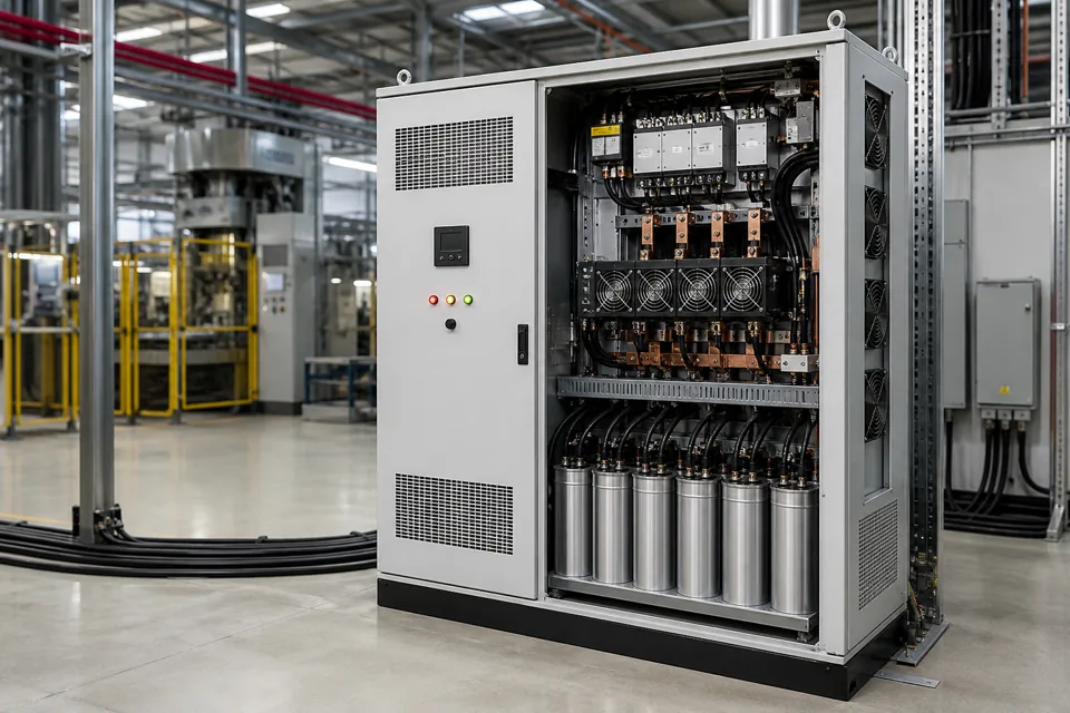
Isolation-transformer selection starts with the intended protective or functional outcome, then coordinates rating, load waveform, shielding, earthing and protection.
- The intended system function should be defined before transformer kVA is selected.
- Secondary earthing and protection are system decisions, not incidental installation details.
- Nonlinear load waveform and inrush can influence rating and protective-device coordination.
Define the separation function and load boundary
Protective separation, functional isolation and noise-control objectives require different system evidence.
State what problem the transformer is intended to solve and which circuits lie on its secondary. Record load kVA, starting events, rectifier or UPS front ends, allowable voltage change and operating environment.
IEC 61558-2-4 addresses general-purpose isolating transformers within its scope and is used with IEC 61558-1. Application-specific equipment can require another product standard or additional rules.
Evidence basis[1] International Electrotechnical Commission[2] International Electrotechnical Commission
Define the separation function and load boundary
Protective separation, functional isolation and noise-control objectives require different system evidence.
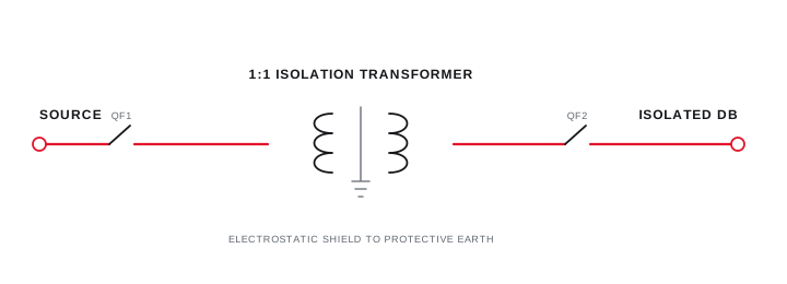
Final ratings, protection, earthing, settings and interlocks follow approved project engineering.
Open full-size SVGDesign the secondary earthing and protection arrangement
Neutral treatment, protective conductors and fault detection determine the behaviour of the separated system.
Define whether and where the secondary is referenced to earth, how protective conductors and bonding are arranged and which protective device clears a fault. Include alternate operating states and connected bypasses.
Do not leave the neutral-earth link to field convention. Record its exact location, conductor, accessibility and relationship to upstream and downstream switching.
Evidence basis[1] International Electrotechnical Commission[2] International Electrotechnical Commission
Design the secondary earthing and protection arrangement
Neutral treatment, protective conductors and fault detection determine the behaviour of the separated system.
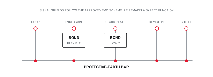
Final ratings, protection, earthing, settings and interlocks follow approved project engineering.
Open full-size SVGCoordinate waveform, inrush and commissioning evidence
Transformer and protective-device selections should tolerate the expected energisation and operating duty.
Review magnetising inrush, load crest factor, harmonic heating, ambient temperature, enclosure ventilation and duty cycle with the manufacturer. Coordinate primary and secondary protection using the declared fault levels and cable data.
At commissioning, verify identity, ratio, polarity, insulation or other specified tests, earthing arrangement and representative load voltage. Retain the test boundary and any untested performance states.
Evidence basis[1] International Electrotechnical Commission[2] International Electrotechnical Commission[3] International Electrotechnical Commission
| Decision | Primary input | Verification |
|---|---|---|
| Function | Required separation outcome | Approved system narrative |
| Rating | Load waveform and duty | Manufacturer selection |
| Earthing | Protective measure | As-built continuity record |
| Protection | Inrush and fault level | Coordinated device schedule |
Information that makes the next review more useful.
- 01
State the required protective, functional, noise-control or voltage-conversion outcome.
- 02
List continuous kVA, starting or inrush duty, crest factor and nonlinear load content.
- 03
Confirm primary and secondary voltage, frequency, phase, vector group and tap requirements.
- 04
Define electrostatic shield, screen termination and enclosure requirements where applicable.
- 05
Document the intended secondary neutral-earth arrangement and downstream protective measure.
- 06
Coordinate inrush, primary and secondary protection, cable duty and fault levels.
- 07
Plan polarity, ratio, insulation, continuity and functional verification within the approved scope.
Standards and technical references.
Links identify the source and scope; access to a complete standard may require purchase or organisational access.
- 01IEC 61558-2-4:2021 — Particular requirements for general-purpose isolating transformersInternational Electrotechnical Commission
- 02IEC 60364-5-54:2011+AMD1:2021 — Earthing arrangements and protective conductorsInternational Electrotechnical Commission
- 03IEC 60364-6:2016 — Verification of low-voltage electrical installationsInternational Electrotechnical Commission
Questions engineers and project teams ask.
Should the secondary neutral of every isolation transformer be earthed?
There is no universal field rule. The earthing and protective arrangement must follow the intended system function, applicable requirements and competent project design.
Can isolation-transformer kVA be selected from running load alone?
Not always. Starting duty, inrush, crest factor, harmonic content, ambient conditions and required voltage performance can affect the equipment selection.