

Thermography becomes useful condition evidence when the image is tied to load, ambient, component identity, comparable references and a safe follow-up decision.
- Load and ambient context are essential to interpreting a thermal pattern.
- Apparent temperature is influenced by surface and viewing conditions as well as electrical behaviour.
- A thermal anomaly initiates a controlled investigation; it does not automatically identify the defective part.
Plan the scan around safe and repeatable access
The inspection boundary determines what can be seen and whether later images can be compared meaningfully.
Define which equipment can be observed in its normal condition and which covers or windows are part of the approved method. Never improvise exposure of energised parts for a better image.
Prepare an asset list and repeatable viewpoints. Include component labels in visible-light frames so a later reviewer can locate the finding without guessing from the thermal palette.
Evidence basis[1] International Electrotechnical Commission[2] National Fire Protection Association
Plan the scan around safe and repeatable access
The inspection boundary determines what can be seen and whether later images can be compared meaningfully.

Final ratings, protection, earthing, settings and interlocks follow approved project engineering.
Open full-size SVGRecord the load and comparison context
Temperature differences are interpreted against operating duty, ambient and comparable components.
Record the operating state and available phase or feeder currents at the time of inspection. Compare similar components under similar loading where the arrangement supports that comparison, and identify imbalance rather than hiding it behind one maximum value.
Reflective surfaces, different finishes, viewing angle and infrared windows can affect apparent temperature. State these limitations in the report instead of presenting the camera reading as contact temperature.
Evidence basis[1] International Electrotechnical Commission[2] National Fire Protection Association
Record the load and comparison context
Temperature differences are interpreted against operating duty, ambient and comparable components.
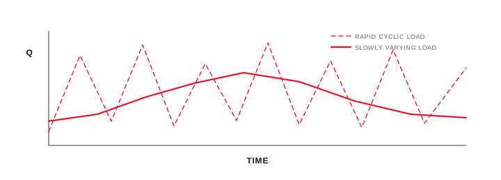
Final ratings, protection, earthing, settings and interlocks follow approved project engineering.
Open full-size SVGClose each anomaly with cause and repair evidence
The finding record connects the thermal pattern to a safe diagnostic action and verified disposition.
Use engineering review to consider load, connection, component, ventilation and surface effects. Assign urgency through the site's maintenance and safety system, not a generic colour scale copied without context.
After corrective work, repeat the observation under a comparable condition where practicable and retain both images, load data and work record.
Evidence basis[1] International Electrotechnical Commission[2] National Fire Protection Association
Information that makes the next review more useful.
- 01
Define the authorised safe-access method, boundaries and equipment condition before scanning.
- 02
Record component identity, load, phase current where available, ambient and operating duration.
- 03
Capture thermal and visible-light images from a repeatable position.
- 04
Use comparable phases, components or ambient references where the configuration supports comparison.
- 05
Note emissivity, reflections, covers, windows and inaccessible areas that limit interpretation.
- 06
Prioritise findings through engineering and safety review rather than image colour alone.
- 07
Retain corrective action and post-repair evidence against the original observation.
Standards and technical references.
Links identify the source and scope; access to a complete standard may require purchase or organisational access.
Questions engineers and project teams ask.
Does the hottest colour in a thermal image identify a fault?
No. Palette colours are relative to the selected scale. Interpretation needs load, ambient, surface, comparison and equipment context plus an appropriate follow-up method.
Can thermography see through a closed metal panel door?
No. It measures infrared radiation from visible surfaces. Approved infrared windows or other monitoring methods may provide a view, subject to their installation and limitations.




