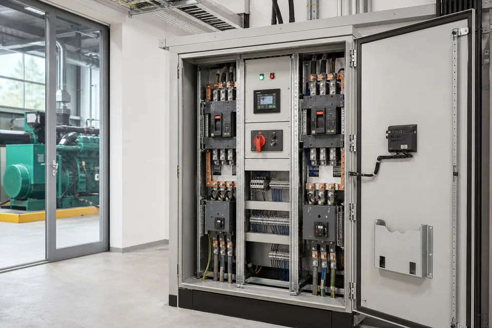
A dependable control-panel architecture connects the machine function to protected power circuits, control logic, field interfaces, construction and verification evidence.
- Architecture starts with the operating function and credible load combinations, not cabinet dimensions.
- Protection selectivity, conductor duty and assembly short-circuit capability must be coordinated with upstream data.
- Power, control and communication segregation should follow voltage, EMC, safety and maintainability needs.
- Verification evidence and project documentation are designed deliverables, not afterthoughts.
Translate operation into functional zones
Group incoming, distribution, motor, control-power, PLC, I/O and communications functions before laying out individual devices.
Map every state transition and identify which function energises, isolates, protects, commands or reports it. Then organise the architecture into power and control zones that support safe access, heat management and clear wiring paths.
Keep maintenance tasks visible: which device is adjusted, which terminals are tested, what remains live after a local isolator opens, and how a failed unit can be replaced without disturbing unrelated wiring.
Translate operation into functional zones
Group incoming, distribution, motor, control-power, PLC, I/O and communications functions before laying out individual devices.

Final ratings, protection, earthing, settings and interlocks follow approved project engineering.
Open full-size SVGCoordinate the protection chain
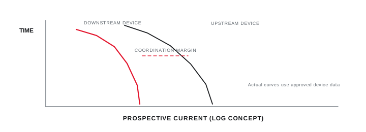
The incoming device, busbar, branch devices and conductors form one fault and overload protection system.
Obtain the prospective fault current or the upstream source and impedance data needed to calculate it. Select the assembly and device capabilities against the real point of installation, including generator or alternate-source conditions where relevant.
Protection coordination considers fault interruption, overload protection, starting currents, discrimination objectives and energy let-through. Final settings and studies require approved manufacturer data and the project electrical model.
Coordinate the protection chain
The incoming device, busbar, branch devices and conductors form one fault and overload protection system.
Final ratings, protection, earthing, settings and interlocks follow approved project engineering.
Open full-size SVGDesign control power and I/O boundaries
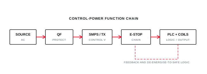
Control supply continuity, protection, reference potential and field interfaces determine how the logic behaves during abnormal states.
Define the source and voltage for PLC, relay, contactor, instrument and network power. Separate safety-related chains and establish the required response to loss of phase, low voltage, emergency stop, communications failure and control-supply recovery.
Create an I/O list with signal type, source, destination, normal state, fail state, isolation and cable responsibility. Network links still need a defined loss-of-communication behaviour and hardwired boundaries where required.
Design control power and I/O boundaries
Control supply continuity, protection, reference potential and field interfaces determine how the logic behaves during abnormal states.
Final ratings, protection, earthing, settings and interlocks follow approved project engineering.
Open full-size SVGPlan segregation, bonding and cable entry
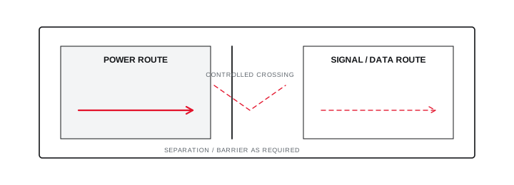
Physical routing should preserve safety, electromagnetic compatibility, inspectability and installation practicality.
Separate high-current power paths from sensitive analogue and communication wiring according to the applicable design rules and equipment guidance. Cross unavoidable paths deliberately and preserve bend radius, termination space and gland access.
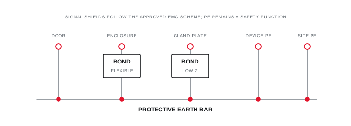
Provide a deliberate protective-bonding system for doors, gland plates and exposed conductive parts. Signal reference and shield treatment follow the system and equipment requirements; they should not be improvised as a substitute for protective earthing.
Plan segregation, bonding and cable entry
Physical routing should preserve safety, electromagnetic compatibility, inspectability and installation practicality.
Final ratings, protection, earthing, settings and interlocks follow approved project engineering.
Open full-size SVGSpecify verification and handover evidence
The accepted assembly needs traceable checks that connect the design basis to the manufactured and tested result.
The IEC 61439 series frames construction and performance requirements plus verification for applicable low-voltage assemblies. The project specification should identify the relevant assembly standard, client requirements and evidence expected from the manufacturer.
Handover can include approved drawings, bills of material, settings, inspection records, routine verification, functional test results, PLC and HMI backups, network parameters and controlled revision history.
Specify verification and handover evidence
The accepted assembly needs traceable checks that connect the design basis to the manufactured and tested result.
Final ratings, protection, earthing, settings and interlocks follow approved project engineering.
Open full-size SVGInformation that makes the next review more useful.
- 01
Functional description, operating sequence, permissives, trips and fail states.
- 02
Incoming source, fault context and complete load schedule.
- 03
Motor starting, drive, heater and switching duties.
- 04
Field I/O, networks, remote interfaces and responsibility boundaries.
- 05
Ambient, enclosure, access, cable and thermal conditions.
- 06
Required verification, drawings, software and handover records.
Standards and technical references.
Links identify the source and scope; access to a complete standard may require purchase or organisational access.
- 01IEC 61439-1:2020 — General rules for low-voltage assembliesInternational Electrotechnical Commission
- 02IEC 61439-2:2020 — Power switchgear and controlgear assembliesInternational Electrotechnical Commission
- 03Central Electricity Authority safety and electric-supply regulations, 2023Central Electricity Authority, Government of India
Questions engineers and project teams ask.
Can control-panel size be finalised before the load and I/O lists?
A preliminary envelope may be discussed, but reliable layout and thermal review depend on device duties, segregation, wiring space, cable entry, access, future allowance and the confirmed functional architecture.
Does using IEC-marked components make the complete panel IEC 61439 compliant?
Component conformity is necessary where applicable but does not by itself verify the complete assembly. Construction, integration and assembly-level requirements and verification still apply.