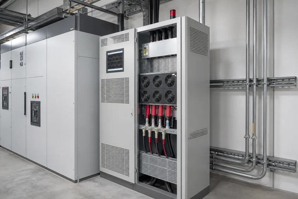
A detuned APFC bank adds series reactors to shift the branch resonance away from targeted network harmonics, but it is not a universal harmonic filter or substitute for measurement.
- Capacitors and network inductance can create a parallel-resonance condition that amplifies harmonic effects.
- A series reactor changes the capacitor branch impedance and shifts its tuning below a selected harmonic order.
- Detuned APFC protects the correction function; it should not be advertised as broad harmonic cancellation without evidence.
- Reactor duty, capacitor voltage, heat and assembly ventilation must be engineered together.
Why capacitors change harmonic behaviour
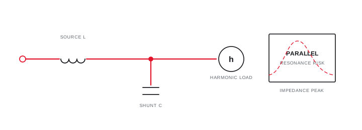
The network has inductance, and adding shunt capacitance changes the frequency-dependent impedance seen by harmonic currents.
At fundamental frequency, the capacitor supplies leading reactive current. At higher frequencies its reactance falls, while inductive reactance rises. The combined network can present a high parallel impedance near a resonant frequency and magnify voltage distortion or capacitor current.
The risk depends on source strength, transformer and feeder impedance, connected capacitance and the harmonic spectrum. A rule based only on the percentage of drive load cannot replace the actual system review.
Why capacitors change harmonic behaviour
The network has inductance, and adding shunt capacitance changes the frequency-dependent impedance seen by harmonic currents.
Final ratings, protection, earthing, settings and interlocks follow approved project engineering.
Open full-size SVGHow the detuned capacitor branch works
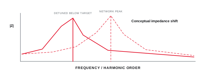
A reactor in series with each capacitor stage moves the branch series-resonant frequency below the harmonic order being avoided.
Below the branch tuning frequency the combination remains capacitive for fundamental-frequency correction. Above it, the branch becomes inductive, reducing the tendency to attract harmonic current at the targeted higher orders.
The reactor changes capacitor voltage and current duty. Component rating, tolerances, losses, temperature rise and ventilation must therefore be checked as one branch rather than adding a reactor to a conventional stage after selection.
How the detuned capacitor branch works
A reactor in series with each capacitor stage moves the branch series-resonant frequency below the harmonic order being avoided.
Final ratings, protection, earthing, settings and interlocks follow approved project engineering.
Open full-size SVGMeasure first and select the response
Detuning, passive filtering and active filtering solve different parts of a harmonic problem.
Record the harmonic spectrum, total demand distortion or the applicable current-distortion metric, voltage distortion, demand and operating state at the correct boundary. IEEE 519 describes steady-state goals at the user PCC; equipment-terminal measurements support a different diagnostic purpose.
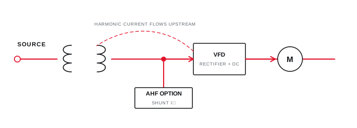
A detuned bank primarily provides power-factor correction in a harmonic-affected network. A tuned passive filter is intentionally designed for selected frequencies, while an active harmonic filter injects compensating current over its designed bandwidth.
Measure first and select the response
Detuning, passive filtering and active filtering solve different parts of a harmonic problem.
Final ratings, protection, earthing, settings and interlocks follow approved project engineering.
Open full-size SVGSpecify thermal and protection boundaries
A complete detuned-bank specification includes the assembly, stage and environmental duties created by harmonic current and reactor losses.
Confirm fault level, incoming protection, branch protection, capacitor and reactor tolerances, switching device duty, conductor sizing, temperature-rise verification and permissible ambient conditions. Define alarm and stage-failure visibility where operational continuity matters.
The final tuning choice and ratings should be documented against approved system information. A website diagram is an educational topology, not a construction drawing or an instruction to retrofit reactors to an energised bank.
Specify thermal and protection boundaries
A complete detuned-bank specification includes the assembly, stage and environmental duties created by harmonic current and reactor losses.
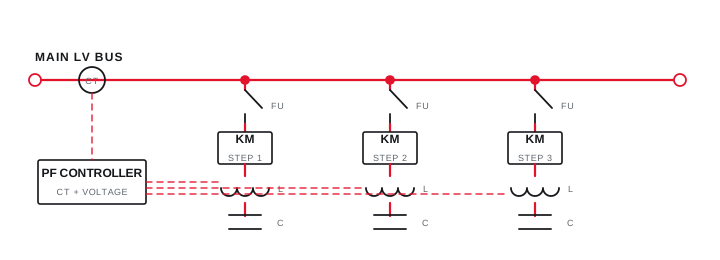
Final ratings, protection, earthing, settings and interlocks follow approved project engineering.
Open full-size SVGInformation that makes the next review more useful.
- 01
Voltage and current harmonic spectrum at identified measurement locations.
- 02
Transformer rating and impedance plus relevant feeder information.
- 03
Existing and proposed capacitor ratings and connection points.
- 04
Inventory of drives, rectifiers, UPS systems, welders and other non-linear loads.
- 05
Operating combinations represented during the measurement period.
- 06
Utility or project harmonic criteria at the applicable boundary.
Standards and technical references.
Links identify the source and scope; access to a complete standard may require purchase or organisational access.
- 01IEC 61642:1997 — Filters and shunt capacitors in harmonic-affected networksInternational Electrotechnical Commission
- 02IEEE 519-2022 — Harmonic control in electric power systemsIEEE Standards Association
- 03IEC 60831-1:2014 — Low-voltage self-healing shunt power capacitorsInternational Electrotechnical Commission
- 04IEEE 1531-2020 — Application and specification of harmonic filtersIEEE Standards Association
Questions engineers and project teams ask.
Does a detuned APFC panel remove all harmonics?
No. Detuning changes the capacitor branch impedance to reduce resonance risk and harmonic loading around the design objective. Harmonic mitigation performance requires a separate measured and verified filter strategy.
Can a detuning percentage be selected without measurements?
Preliminary options can be discussed from the load inventory and network data, but final tuning and duty should follow the system impedance, capacitor rating, harmonic spectrum and applicable project criteria.