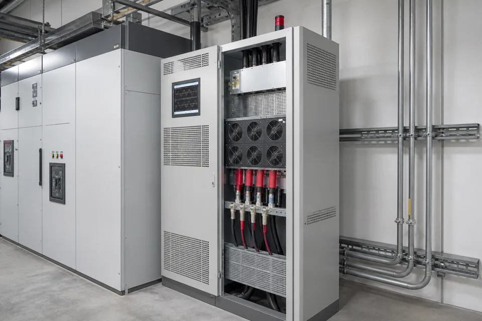
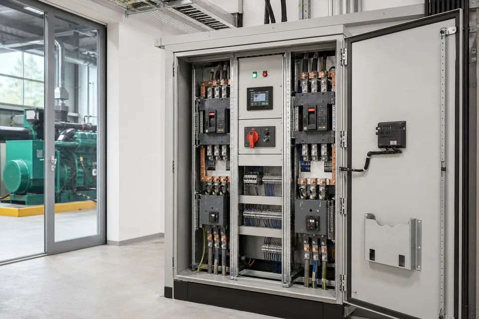
Generator harmonic assessment connects the alternate source impedance and regulator behaviour to the actual nonlinear load mix and staged operating sequence.
- Generator mode changes the source impedance and can change voltage distortion for the same load current.
- A staged operating sequence is part of the harmonic model, not merely an operational detail.
- PCC limits and in-plant generator compatibility are related but are not interchangeable acceptance tests.
Map the active source and nonlinear load states
The harmonic boundary changes with source, network configuration and which converters are operating.
Record whether the system is on utility, generator, parallel operation or a transfer state. For each, identify transformer or alternator impedance, cable path, connected capacitors and the actual load groups in service.
IEC 61000-2-4 provides industrial in-plant compatibility context for low-frequency conducted disturbances. IEEE 519 frames steady-state goals at the user PCC; it should not be copied as a generator-terminal equipment guarantee.
Evidence basis[1] International Electrotechnical Commission[2] IEEE Standards Association
Map the active source and nonlinear load states
The harmonic boundary changes with source, network configuration and which converters are operating.
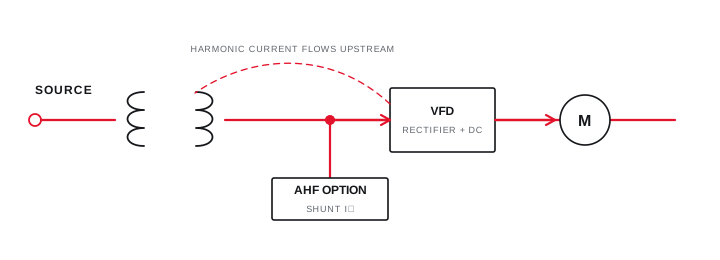
Final ratings, protection, earthing, settings and interlocks follow approved project engineering.
Open full-size SVGMeasure current and voltage at coordinated boundaries
Current spectrum identifies load contribution while voltage spectrum shows the source-network response.
Measure three-phase voltage and current with a declared aggregation method and operating-state log. Capture frequency, imbalance, RMS values, harmonic spectrum and short events during load acceptance.
Compare generator and utility modes only when the active load mix is known. A higher voltage THD value with a similar current spectrum can indicate the effect of a weaker source rather than a new load emission.
Evidence basis[1] International Electrotechnical Commission[2] IEEE Standards Association[3] International Electrotechnical Commission
Measure current and voltage at coordinated boundaries
Current spectrum identifies load contribution while voltage spectrum shows the source-network response.
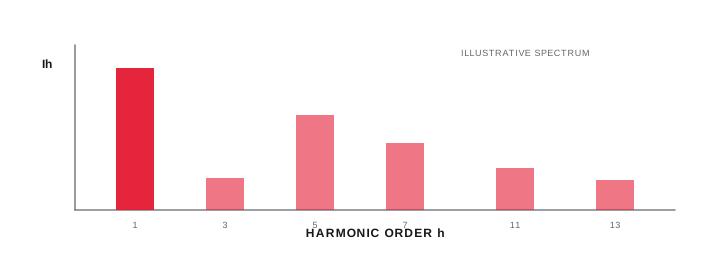
Final ratings, protection, earthing, settings and interlocks follow approved project engineering.
Open full-size SVGEvaluate source, sequence and mitigation together
The preferred response may change source capability, load sequence, converter configuration or filtering.
Review alternator selection, voltage-regulator response, staged loading, line reactors, converter front ends and active or passive mitigation as a coordinated system. Confirm that any capacitor or filter remains suitable in each source state.
Validate the proposed arrangement with manufacturer data and a project model before procurement. Commissioning should then repeat the named operating states and boundaries used in the design assessment.
Evidence basis[1] International Electrotechnical Commission[2] IEEE Standards Association[3] International Electrotechnical Commission
| Evidence | Question answered | Common limitation |
|---|---|---|
| Current spectrum | What loads inject | Requires load-state log |
| Voltage spectrum | How source responds | Boundary dependent |
| Event trace | What occurs during steps | Not steady-state evidence |
| Manufacturer data | Permitted source duty | Model specific |
Information that makes the next review more useful.
- 01
Collect generator alternator, reactance, regulator and allowable nonlinear-load information from the manufacturer.
- 02
List rectifier, UPS, VFD, charger and converter loads by operating state and front-end topology where known.
- 03
Map the staged load-acceptance sequence, largest steps and motor-starting events.
- 04
Measure voltage and current waveforms on utility and generator at named boundaries under comparable states.
- 05
Retain harmonic spectrum, RMS values, imbalance, frequency and event timing rather than THD alone.
- 06
Identify capacitors, passive filters and existing active compensation connected in generator mode.
- 07
Review the model and any mitigation with the generator and converter suppliers before implementation.
Standards and technical references.
Links identify the source and scope; access to a complete standard may require purchase or organisational access.
- 01IEC 61000-2-4:2024 — Compatibility levels for industrial power-distribution systemsInternational Electrotechnical Commission
- 02IEEE 519-2022 — Harmonic control in electric power systemsIEEE Standards Association
- 03IEC 61000-4-30:2025 — Power-quality measurement methodsInternational Electrotechnical Commission
Questions engineers and project teams ask.
Why can voltage distortion rise when the plant transfers to a generator?
The generator path usually has different impedance and regulator dynamics, so the same nonlinear current can produce a different voltage waveform at the measured bus.
Is generator harmonic assessment the same as IEEE 519 compliance?
No. IEEE 519 addresses steady-state goals at the user PCC. Generator-mode compatibility and equipment performance require their own named boundaries and manufacturer data.