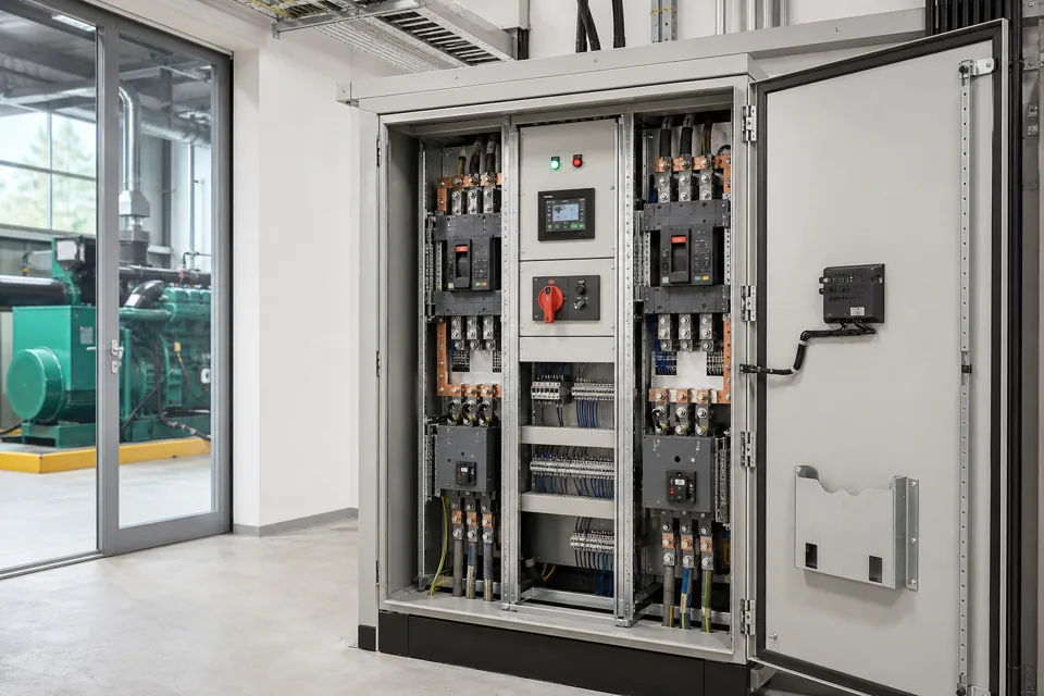
A useful electrical handover set links the installed system to controlled drawings, equipment identifiers, settings, test records and unresolved limitations.
- As-built status is a controlled claim about the installed state and document revision.
- Settings and test evidence need equipment and revision identity to remain useful.
- Open deviations should remain visible rather than disappearing behind a general handover certificate.
Build one controlled information index
Document number, revision, status and owner prevent conflicting files from becoming parallel truths.
List every drawing, schedule, register, software backup, setting export and test record with its current status. Distinguish approved design, redline, as-built and superseded documents explicitly.
IEC 61082-1 provides rules for presenting information in electrotechnical documents. A project document-control convention still needs naming, revision, approval and native-file requirements.
Evidence basis[1] International Electrotechnical Commission[2] International Electrotechnical Commission
Build one controlled information index
Document number, revision, status and owner prevent conflicting files from becoming parallel truths.

Final ratings, protection, earthing, settings and interlocks follow approved project engineering.
Open full-size SVGReconcile the installed field condition
A systematic walkdown closes differences between drawings, labels, settings and physical connections.
Trace source, feeder, cable, terminal and equipment identifiers against the drawings. Incorporate approved changes and retain unresolved differences as controlled punch items with location and consequence.
Export device settings and software using the equipment identifier and date. A screenshot without model, firmware, project file or checksum can be difficult to restore later.
Evidence basis[1] International Electrotechnical Commission[2] International Electrotechnical Commission[3] International Electrotechnical Commission
Reconcile the installed field condition
A systematic walkdown closes differences between drawings, labels, settings and physical connections.

Final ratings, protection, earthing, settings and interlocks follow approved project engineering.
Open full-size SVGPackage evidence for operation and future change
The final set should help an authorised team operate, isolate, troubleshoot and modify the system safely.
Link FAT, installation, commissioning and functional records to the equipment and document revision they test. Include exceptions, untested states and calibration information where relevant.
Provide native and viewable files under controlled access, plus a read-me that identifies the authoritative set. Confirm the recipient can open the files and recover the software before closing handover.
Evidence basis[1] International Electrotechnical Commission[2] International Electrotechnical Commission[3] International Electrotechnical Commission
| Record group | Purpose | Control |
|---|---|---|
| Drawings | Understand installed topology | Revision and as-built status |
| Settings | Recover equipment configuration | Model and export date |
| Tests | Show verified functions | Equipment and scenario link |
| Open items | Preserve limitations | Owner and due state |
Information that makes the next review more useful.
- 01
Create one document index with number, title, revision, status, owner and file location.
- 02
Reconcile single-lines, schematics, layouts, terminal plans, cable schedules and equipment registers.
- 03
Mark every redline incorporated, superseded or retained as an unresolved field deviation.
- 04
Retain final protection, controller, drive and instrument settings in exportable form where available.
- 05
Link inspection, FAT, SAT and commissioning records to the equipment and revision tested.
- 06
Include operating sequences, maintenance information, spare parts and recovery instructions within scope.
- 07
Record open items, limitations, approvals and the controlled native source files at handover.
Standards and technical references.
Links identify the source and scope; access to a complete standard may require purchase or organisational access.
- 01IEC 61082-1:2014 — Rules for electrotechnical diagrams, drawings and tablesInternational Electrotechnical Commission
- 02IEC 60364-6:2016 — Verification of low-voltage electrical installationsInternational Electrotechnical Commission
- 03IEC 61439-2:2020 — Power switchgear and controlgear assembliesInternational Electrotechnical Commission
Questions engineers and project teams ask.
What makes an electrical drawing genuinely as-built?
It has a controlled revision and status, reflects verified installed conditions, incorporates approved changes and keeps unresolved deviations visible.
Should equipment settings be included in the handover package?
Where within scope, retain model-linked exports or controlled records with date, revision and access information so authorised teams can recover the installed configuration.