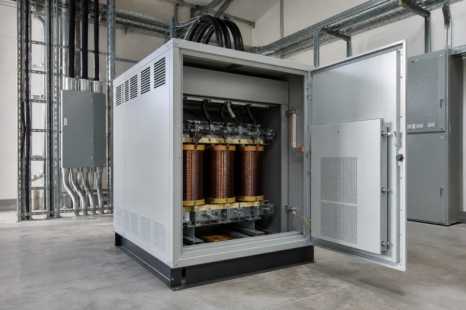
An earthing inspection connects the declared system arrangement to the actual protective-conductor path, bonding joints and verification records.
- The system earthing arrangement defines what protective paths should exist.
- Visual inspection and measured continuity answer different parts of the verification question.
- A resistance value is incomplete without the test path, method, instrument and acceptance basis.
Declare the source and protective arrangement
The inspection path follows from the verified source earthing and selected protective measures.
Start from the transformer, generator or incoming supply and document the neutral-earth relationship, main earthing terminal and protective-conductor routes. Include alternate-source and transfer states where they change the arrangement.
IEC 60364-5-54 addresses earthing arrangements and protective conductors within its scope. The applicable local rules and project design still define the required values and conductor selection.
Evidence basis[1] International Electrotechnical Commission[2] International Electrotechnical Commission
Declare the source and protective arrangement
The inspection path follows from the verified source earthing and selected protective measures.
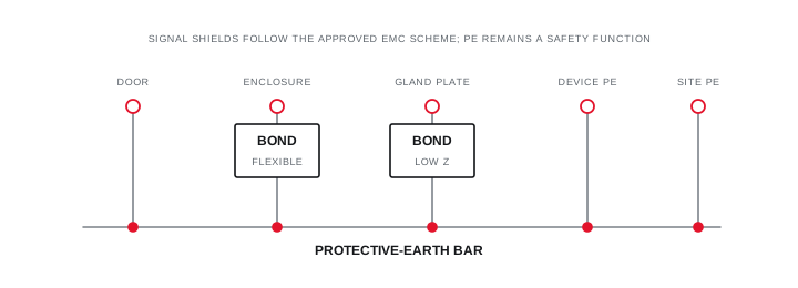
Final ratings, protection, earthing, settings and interlocks follow approved project engineering.
Open full-size SVGInspect every intentional bonding path
Conductor identity, joint condition and mechanical continuity should be visible in the field record.
Trace conductors to enclosures, doors, gland plates, cable armour and exposed conductive parts included in the design. Record missing labels, painted interfaces, damaged braids, corrosion and joints that cannot be inspected.
Do not assume a hinge, mounting bolt or cable gland provides the intended path unless the design and construction establish it. Photograph the exact termination and reference it to the drawing or equipment tag.
Evidence basis[1] International Electrotechnical Commission[3] International Electrotechnical Commission
Inspect every intentional bonding path
Conductor identity, joint condition and mechanical continuity should be visible in the field record.

Final ratings, protection, earthing, settings and interlocks follow approved project engineering.
Open full-size SVGMeasure through a controlled verification record
Test method, isolation state, path and acceptance basis make continuity results interpretable.
Plan continuity and other applicable tests under an authorised procedure. State the test points, instrument, compensation for leads where relevant, circuit condition and any connected parallel paths.
Record measured values alongside the project acceptance basis and restoration checks. A general statement that earthing is satisfactory should not replace the traceable result set.
Evidence basis[1] International Electrotechnical Commission[2] International Electrotechnical Commission[3] International Electrotechnical Commission
| Stage | Evidence | Common gap |
|---|---|---|
| Arrangement | Verified single-line | Alternate source omitted |
| Visual path | Tagged conductors and joints | Hidden or painted interface |
| Measurement | Method and test points | Unstated parallel path |
| Closeout | Restoration and exceptions | Generic pass statement |
Information that makes the next review more useful.
- 01
Confirm the declared source earthing arrangement and protective measure from approved documentation.
- 02
Trace main earthing, protective and bonding conductors with their identified termination points.
- 03
Record conductor material, cross-section, routing, protection and connection method.
- 04
Inspect joints for accessibility, corrosion, looseness, paint, damage and unauthorised disconnection.
- 05
Identify removable doors, gland plates, cable armour and structural interfaces requiring an intentional path.
- 06
Plan continuity or other verification with isolation, instrument and test-current conditions stated.
- 07
Retain measured results, limits, exceptions and restoration evidence in the inspection record.
Standards and technical references.
Links identify the source and scope; access to a complete standard may require purchase or organisational access.
- 01IEC 60364-5-54:2011+AMD1:2021 — Earthing arrangements and protective conductorsInternational Electrotechnical Commission
- 02IEC 60364-6:2016 — Verification of low-voltage electrical installationsInternational Electrotechnical Commission
- 03IEC 61439-1:2020 — General rules for low-voltage assembliesInternational Electrotechnical Commission
Questions engineers and project teams ask.
Does a visual earth connection prove protective continuity?
No. Visual inspection can confirm routing and joint condition, while an authorised measurement is needed where the verification plan requires continuity evidence.
Can one earth resistance value represent the whole installation?
No. The relevant tests depend on the system arrangement and protective measure, and every value needs named test points, method, conditions and acceptance basis.