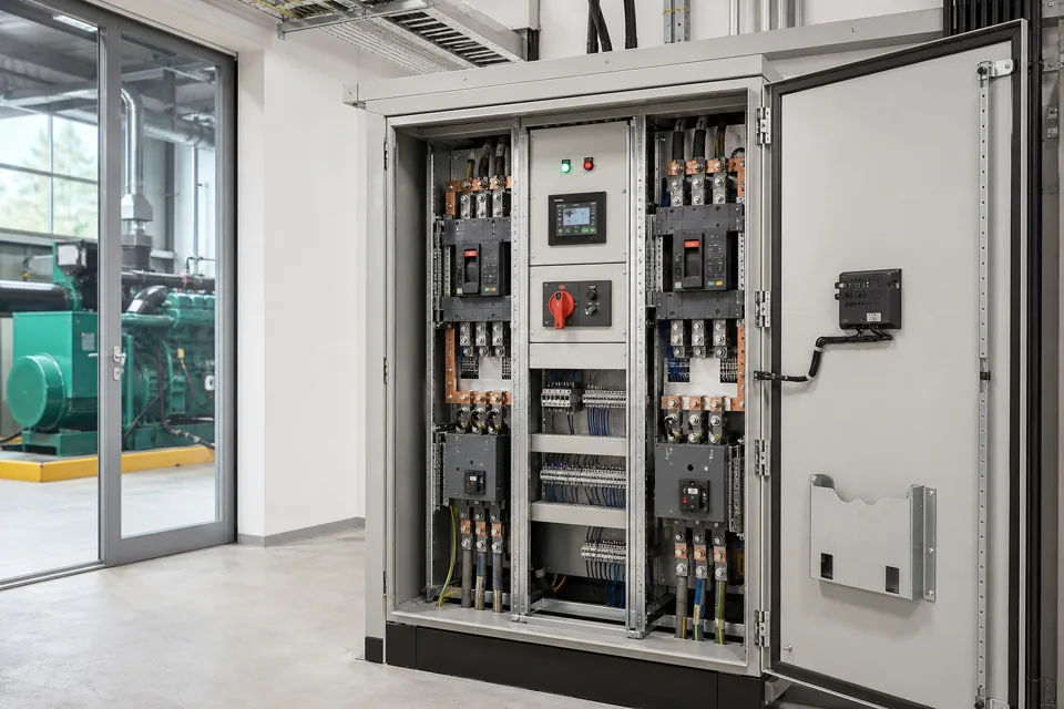
Control power and protective earthing solve different functions: the control chain defines behaviour under loss and restoration, while protective conductors and bonding support electric-shock protection.
- Control-power restoration should not create an unintended machine or process restart.
- Protective earth remains a safety function even when functional references and shields are present.
- Door and removable-part bonding must remain effective through the intended mechanical life and maintenance states.
Map the complete control-power function chain
Source, protection, conversion, emergency chain, logic and output devices must have defined states for normal operation, loss and restoration.
Draw control power from its source through protective devices, transformer or SMPS, emergency-stop or safety chain, PLC and output coils. Identify external supplies and back-fed signals that can keep part of the circuit alive after the main isolator is open.
For each output, define de-energised state, retained energy, feedback and restart permission. Where automatic recovery is required, document the conditions that make it safe and the interfaces responsible for that decision.
Evidence basis[1] International Electrotechnical Commission[2] International Electrotechnical Commission
Map the complete control-power function chain
Source, protection, conversion, emergency chain, logic and output devices must have defined states for normal operation, loss and restoration.
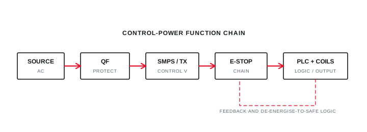
Final ratings, protection, earthing, settings and interlocks follow approved project engineering.
Open full-size SVGBuild a deliberate protective-bonding network
Exposed conductive parts connect through verified protective conductors and bonding paths to the installation protective-earth interface.
Provide a defined PE bar and bonding paths for the enclosure, doors, removable plates and devices. Paint, hinges or incidental mounting hardware should not be assumed to provide the intended protective continuity unless the verified design establishes it.
Size and route protective conductors using the applicable installation and equipment rules. Keep connections accessible for inspection and protected against loosening, corrosion and mechanical damage.
Evidence basis[1] International Electrotechnical Commission[3] International Electrotechnical Commission[4] Central Electricity Authority, Government of India
Build a deliberate protective-bonding network
Exposed conductive parts connect through verified protective conductors and bonding paths to the installation protective-earth interface.
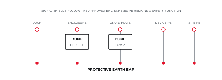
Final ratings, protection, earthing, settings and interlocks follow approved project engineering.
Open full-size SVGSeparate PE, functional reference and shield decisions
A functional earth or cable shield termination serves EMC or signal integrity and must be documented alongside, not instead of, protective bonding.
Identify shield termination at both ends or one end according to the approved EMC scheme and equipment documentation. High-frequency bonding and low-frequency ground-loop concerns can lead to different connection methods; there is no universal one-end rule.
Use distinct symbols and terminal designations for PE, functional earth, clean reference and signal common. Verify continuity and functional performance using separate acceptance steps so a signal test does not become mistaken evidence of protective bonding.
Evidence basis[1] International Electrotechnical Commission[2] International Electrotechnical Commission[3] International Electrotechnical Commission
Information that makes the next review more useful.
- 01
Identify every control-power source, voltage, protective device, transformer or power supply and backup path.
- 02
Define the required state for outputs, valves, drives and contactors after control-power loss.
- 03
Define manual or automatic restart conditions after supply restoration.
- 04
List enclosure, door, gland plate, DIN rail and device protective-bonding connections.
- 05
Mark protective earth, functional earth, signal common and shield terminations distinctly.
- 06
Record external PE conductor, neutral and earthing-system information at the panel interface.
- 07
Plan continuity, polarity, insulation and functional tests under an approved safe method.
Standards and technical references.
Links identify the source and scope; access to a complete standard may require purchase or organisational access.
- 01IEC 60204-1:2016 — Electrical equipment of machinesInternational Electrotechnical Commission
- 02IEC 61439-1:2020 — General rules for low-voltage assembliesInternational Electrotechnical Commission
- 03IEC 60364-5-54:2011 — Earthing arrangements and protective conductorsInternational Electrotechnical Commission
- 04Central Electricity Authority safety and electric-supply regulations, 2023Central Electricity Authority, Government of India
Questions engineers and project teams ask.
Can a panel door rely on hinges for protective bonding?
Only if the verified design establishes that path. A deliberate flexible bonding conductor is commonly used where door-mounted equipment or the required continuity makes incidental hinge contact unsuitable.
Should every cable shield be connected at one end only?
No. Shield termination depends on frequency, equipment, EMC environment and approved architecture. Document the purpose and follow the applicable equipment and project guidance.