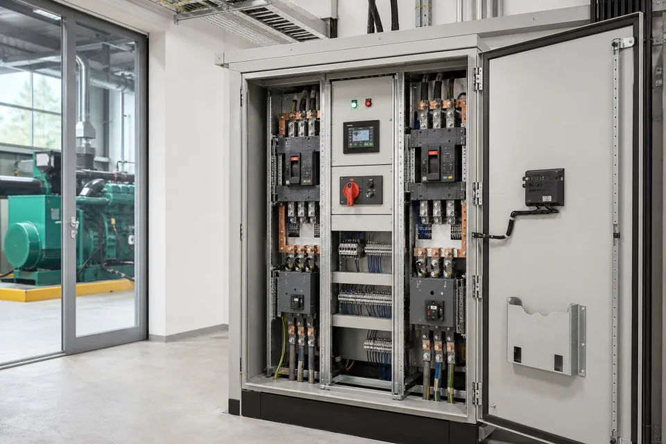
A useful control-panel enquiry explains what the system must operate, the electrical supply and loads, the required sequence, interfaces and installation conditions.
- Function, load and sequence information is more useful than a component-brand list on its own.
- Unknown site conditions should be recorded as verification actions instead of silently assumed.
- Drawings, testing, delivery and installation boundaries belong in the requirement from the beginning.
Begin with the operating function
Describe what the panel must make possible before selecting an enclosure, device family or control platform.
State which machine, process, utility or distribution system the panel serves and what a normal operating cycle looks like. Include start, stop, permissive, trip, reset and emergency states where they affect the electrical design.
Separate required outcomes from preferred component makes. Approved brands can be an important project constraint, but they do not replace the current, duty, protection, interface and environmental information needed to engineer an assembly.
Identify every incoming source and the conditions under which each source is available.
List controlled loads, operating combinations, interlocks and feedback signals.
Mark responsibility boundaries between the panel, field devices, machine supplier and plant system.
Begin with the operating function
Describe what the panel must make possible before selecting an enclosure, device family or control platform.

Final ratings, protection, earthing, settings and interlocks follow approved project engineering.
Open full-size SVGAssemble the electrical and protection data
The single-line diagram and load schedule connect the stated function to conductors, protection and switching devices.
Provide nominal voltage, frequency, phase arrangement, earthing information and the available fault-current or upstream protection data when known. Motor schedules should include rated power, current, starting method, duty and any drive or soft-starter interface.
The required assembly rating cannot be inferred reliably from connected kilowatts alone. Simultaneous demand, starting current, utilisation, diversity, ambient temperature, installation method and future additions all influence the engineering review.
| Information group | Useful input | Why it matters |
|---|---|---|
| Supply | Voltage, frequency, phases, source and fault data | Defines insulation, switching and protection context |
| Loads | Current, duty, starting and operating combinations | Shapes feeder, busbar and thermal requirements |
| Control | Sequence, I/O, communications and fail states | Defines logic and interface boundaries |
| Site | Ambient, enclosure, cable entry and access | Affects construction and installation arrangement |
Assemble the electrical and protection data
The single-line diagram and load schedule connect the stated function to conductors, protection and switching devices.

Final ratings, protection, earthing, settings and interlocks follow approved project engineering.
Open full-size SVGClose interfaces and deliverables
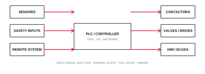
A complete scope identifies what must be supplied, checked, documented and coordinated outside the enclosure.
List field devices, remote panels, PLC or supervisory systems, volt-free contacts, analogue signals, network protocols and any hardwired safety chain. Define who supplies, powers, terminates, configures and tests each interface.
Record required drawing formats, review stages, routine checks, factory acceptance activity, packing, delivery, installation supervision and handover documents. A clear deliverable list reduces late commercial and programme ambiguity.
Include cable schedules and terminal responsibility where field wiring is part of the project.
Define software, passwords, backups and source-file handover expectations before programming begins.
State whether shutdown, access, lifting, storage and energisation support are client or supplier responsibilities.
Close interfaces and deliverables
A complete scope identifies what must be supplied, checked, documented and coordinated outside the enclosure.
Final ratings, protection, earthing, settings and interlocks follow approved project engineering.
Open full-size SVGInformation that makes the next review more useful.
- 01
Describe the equipment, utility or process the panel must control or distribute power to.
- 02
Share the latest single-line diagram, load list and available project specification.
- 03
State the system voltage, frequency, phases and known fault or protection requirements.
- 04
Explain the operating sequence, interlocks, local or remote controls and indications.
- 05
List incoming and outgoing circuits, motor data, starting methods and external interfaces.
- 06
Record enclosure location, ambient conditions, access, cable entry and available space.
- 07
Identify the required drawings, checks, delivery location, schedule and site responsibilities.
Standards and technical references.
Links identify the source and scope; access to a complete standard may require purchase or organisational access.
- 01IEC 61439-1:2020 — General rules for low-voltage assembliesInternational Electrotechnical Commission
- 02IEC 61439-2:2020 — Power switchgear and controlgear assembliesInternational Electrotechnical Commission
- 03Central Electricity Authority safety and electric-supply regulations, 2023Central Electricity Authority, Government of India
Questions engineers and project teams ask.
Can I enquire without a completed single-line diagram?
Yes. Share the information already available and describe the required outcome. The initial review can identify which missing inputs are necessary before configuration or quotation.
Should component brands be specified in the first enquiry?
Include approved makes or client standards when they exist. Otherwise describe the functional, protection, interface and documentation requirements first so selection is not based on brand alone.