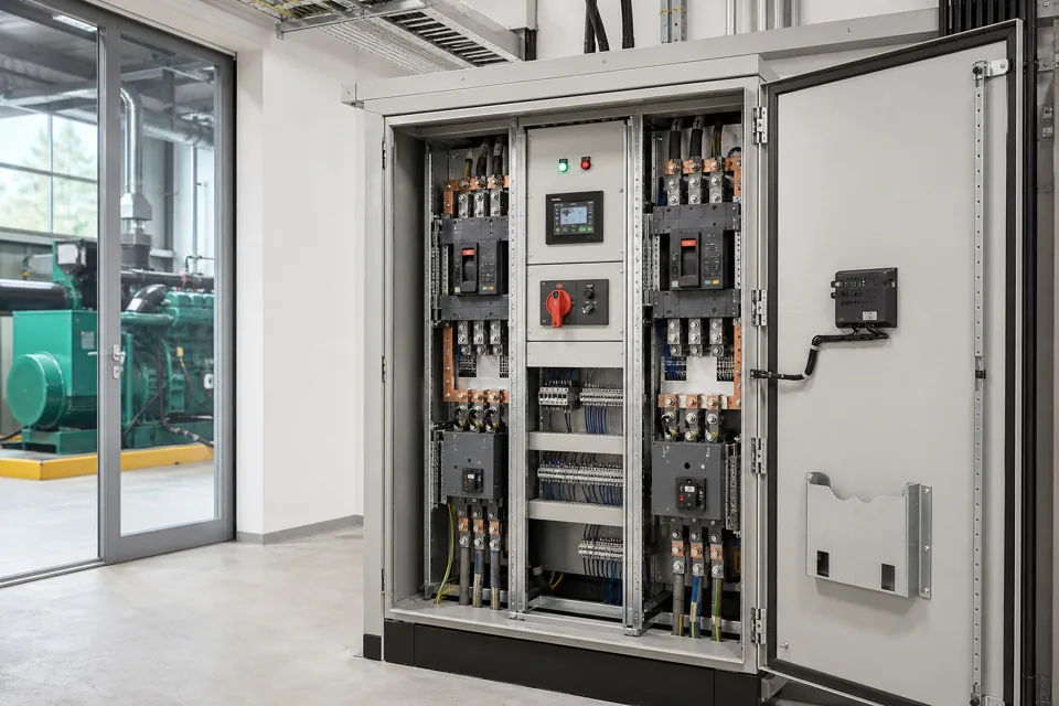
Effective cable segregation coordinates power, control, analogue, communication and converter circuits around coupling paths and verified interface requirements.
- Circuit classification should drive routing, not cable colour or convenience.
- Shield termination, bonding and filter placement are part of the same coupling-path design.
- The as-built inspection must include field cable transitions outside the panel.
Classify circuits by emission and susceptibility
Power level alone does not describe switching edges, common-mode current or signal sensitivity.
Create route classes for mains and motor power, switched inductive circuits, DC control, analogue measurement, encoder or pulse signals and communication networks. Identify circuits with high dv/dt or di/dt and those carrying small or high-impedance signals.
IEC TR 61000-5-2 provides installation guidance for EMC earthing and cabling. IEC 61800-3 addresses adjustable-speed drive EMC within its scope and should be read with the drive manufacturer's installation instructions.
Evidence basis[1] International Electrotechnical Commission[2] International Electrotechnical Commission
Classify circuits by emission and susceptibility
Power level alone does not describe switching edges, common-mode current or signal sensitivity.
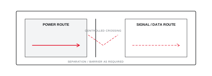
Final ratings, protection, earthing, settings and interlocks follow approved project engineering.
Open full-size SVGControl the complete coupling path
Separation works with source suppression, shields, reference planes, bonding and filter placement.
Keep source and victim routes apart for the practical parallel length, cross at a controlled angle where necessary and avoid long shared loops. Place filters and suppression devices so unfiltered and filtered wiring do not recouple.
Follow the specified shield termination at both panel and field ends. A drain wire, pigtail or single-end termination may be unsuitable at high frequency even when it appears electrically connected at power frequency.
Evidence basis[1] International Electrotechnical Commission[2] International Electrotechnical Commission[3] International Electrotechnical Commission
Control the complete coupling path
Separation works with source suppression, shields, reference planes, bonding and filter placement.

Final ratings, protection, earthing, settings and interlocks follow approved project engineering.
Open full-size SVGVerify the as-built interface under operation
Inspection and functional evidence should focus on named symptoms and representative switching states.
Inspect internal duct fill, spare-wire routing, gland entry, shield clamps, door crossings and the field tray beyond the enclosure. Update the routing record when installation constraints force a deviation.
Test the interfaces most likely to reveal coupling—analogue stability, encoder counts, communication errors or nuisance input changes—while representative drives and contactors operate. Record the operating state and observed result.
Evidence basis[1] International Electrotechnical Commission[2] International Electrotechnical Commission[3] International Electrotechnical Commission
| Circuit class | Primary concern | Evidence |
|---|---|---|
| Motor and converter | Fast switching and common mode | Cable and shield route |
| Analogue | Low-level coupled noise | Separation and trend |
| Communication | Reference and burst immunity | Topology and error log |
| Relay and solenoid | Inductive switching transient | Suppression and routing |
Information that makes the next review more useful.
- 01
Classify each circuit by function, voltage, current, switching edge and sensitivity.
- 02
Identify VFD, contactor, relay, transformer and power-supply emission sources.
- 03
Map analogue, pulse, encoder, communication and safety-related signal routes.
- 04
Apply equipment-manufacturer shield, gland, filter and motor-cable instructions.
- 05
Plan tray, duct and panel-zone separation with controlled crossings and transition points.
- 06
Record the protective and functional bonding concept without conflating their purposes.
- 07
Inspect the as-built routing and test named interfaces under representative operation.
Standards and technical references.
Links identify the source and scope; access to a complete standard may require purchase or organisational access.
- 01IEC TR 61000-5-2:1997 — EMC earthing and cabling installation guidelinesInternational Electrotechnical Commission
- 02IEC 61800-3:2022 — EMC requirements for adjustable-speed power drive systemsInternational Electrotechnical Commission
- 03IEC 61439-1:2020 — General rules for low-voltage assembliesInternational Electrotechnical Commission
Questions engineers and project teams ask.
Is one fixed cable separation distance suitable for every panel?
No. Circuit emission, susceptibility, parallel length, cable construction, shielding, bonding and equipment instructions determine the project routing controls.
Does cable segregation replace shielding and suppression?
No. Segregation is one part of the coupling-path design and must be coordinated with source suppression, shield termination, bonding, filtering and equipment immunity.