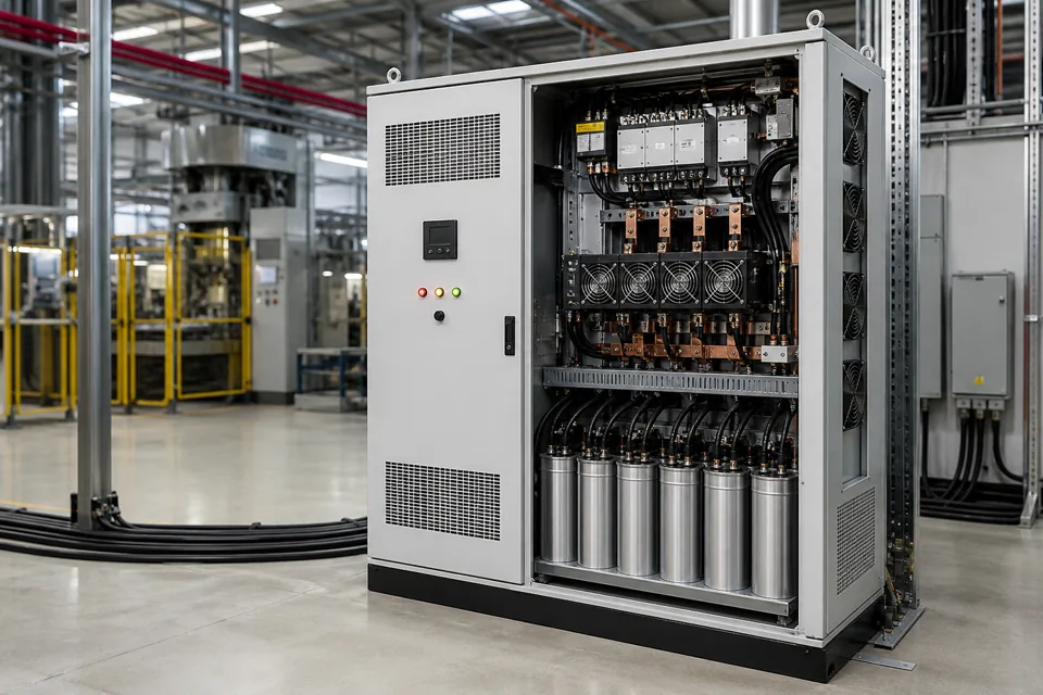
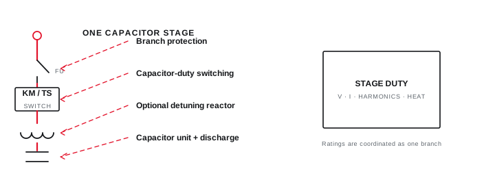
A capacitor stage is not an ordinary steady load: energisation can create high transient current, while trapped charge and rapid re-switching can increase stress across the switching device and capacitor.
- Capacitor energisation can impose transient duty far above steady-state branch current.
- A controller's minimum off-time protects the physical discharge and re-switching process.
- Use capacitor-duty switching data; a generic contactor current rating is not enough.
Understand why energisation creates inrush
At closing, the network and capacitor voltage difference drives a transient limited by the complete circuit impedance.
A discharged capacitor initially behaves as a low-impedance path at the instant of connection. If other stages are already energised on the same bus, they can contribute back-to-back switching current through a short, low-impedance path. The resulting peak is a transient event, not the same as the stage's continuous current.
Purpose-designed capacitor contactors often introduce pre-insertion impedance before the main contacts close. Thyristor modules use a different controlled switching method. Either approach still needs verified voltage, current, thermal and short-circuit coordination.
Evidence basis[1] International Electrotechnical Commission[2] International Electrotechnical Commission[3] Eaton
Understand why energisation creates inrush
At closing, the network and capacitor voltage difference drives a transient limited by the complete circuit impedance.
Final ratings, protection, earthing, settings and interlocks follow approved project engineering.
Open full-size SVGCoordinate discharge and the next closing command
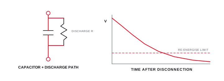
The controller must not reconnect a stage until residual voltage has fallen to the level assumed by the switching design.
Discharge resistors or an approved discharge device reduce retained voltage after isolation. The time required depends on the capacitor and discharge arrangement; it should come from the component data and be reflected in controller lockout timing.
A rapid load cycle does not justify shortening the off-time below the branch capability. If the application requires sub-cycle or very frequent response, the engineering decision may move toward a purpose-designed thyristor-switched bank, SVG or another response after the actual objective is measured.
Evidence basis[1] International Electrotechnical Commission[2] International Electrotechnical Commission
Coordinate discharge and the next closing command
The controller must not reconnect a stage until residual voltage has fallen to the level assumed by the switching design.
Final ratings, protection, earthing, settings and interlocks follow approved project engineering.
Open full-size SVGSpecify the complete branch duty
Continuous current, transient making duty, switching life, protection, temperature and fault behaviour belong in one branch schedule.
Use capacitor and switching-device application data to establish ratings. Include harmonic current, capacitor tolerance, possible overvoltage, reactor losses, enclosure temperature and the number of operations expected from the controller sequence.
Acceptance evidence can include component records, wiring checks, discharge timing, manual switching observations, thermal inspection under a defined load and confirmation that the controller does not issue an immediate unsafe reclose.
Evidence basis[1] International Electrotechnical Commission[2] International Electrotechnical Commission[3] Eaton
| Input | Why it matters | Evidence |
|---|---|---|
| Stage kVAr and voltage | Defines continuous capacitor current | Nameplate and approved schedule |
| Other energised stages | Changes back-to-back inrush path | Single-line and sequence |
| Minimum off-time | Allows the intended discharge | Capacitor and controller data |
| Operations per hour | Affects thermal and life duty | Measured load-cycle log |
Information that makes the next review more useful.
- 01
List each stage kVAr, rated voltage, frequency and capacitor construction.
- 02
Identify the proposed switching device and its capacitor-duty application data.
- 03
Record upstream impedance, nearby energised stages and any series reactor in the branch.
- 04
Define the minimum off-time and prove the discharge path before re-energisation.
- 05
Estimate switching operations from the real load cycle rather than a single daily average.
- 06
Review harmonic current and ambient temperature with the continuous-current duty.
- 07
Include failed-discharge, welded-device and loss-of-control-power states in the review.
Standards and technical references.
Links identify the source and scope; access to a complete standard may require purchase or organisational access.
Questions engineers and project teams ask.
Why is a capacitor contactor different from a general contactor?
Capacitor-duty contactors are applied for the transient and repeated switching behaviour of capacitor stages, often with an inrush-limiting arrangement. Selection still follows the manufacturer's specific capacitor application data.
Can a disconnected capacitor stage be reconnected immediately?
Only when the branch and controller are designed for that duty. Conventional stages need the specified discharge and lockout time; rapid applications may require a different switching technology.