Adding shunt capacitance changes the network impedance and can move a parallel-resonance point near an existing harmonic order, so source strength, bank kVAr and measured spectrum should be reviewed together.
- A capacitor bank changes the network frequency response even when its purpose is only power-factor correction.
- An approximate resonance order is a screening signal, not a final filter or reactor design.
- Measure the existing harmonic spectrum before deciding that detuning is or is not required.
Understand the parallel-resonance mechanism
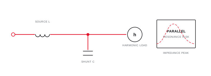
Source inductance and shunt capacitance create a frequency at which the network impedance can rise and amplify existing harmonic excitation.
The upstream transformer and supply contribute inductive impedance, while the capacitor bank contributes capacitive impedance. At a frequency where their effects approach balance, the bus can present high parallel impedance. A harmonic current source near that frequency may then produce greater voltage distortion and capacitor current.
The bank does not need to generate harmonics to participate in the problem. Non-linear loads supply the excitation, while the changed impedance determines how strongly the network responds.
Evidence basis[1] International Electrotechnical Commission[2] International Electrotechnical Commission
Understand the parallel-resonance mechanism
Source inductance and shunt capacitance create a frequency at which the network impedance can rise and amplify existing harmonic excitation.
Final ratings, protection, earthing, settings and interlocks follow approved project engineering.
Open full-size SVGUse source strength and bank size as a screen
Approximate calculations can indicate whether a proposed bank places resonance near a characteristic harmonic order, but they do not replace a full network model.
A common preliminary relationship estimates the resonance order from short-circuit strength and total capacitor kVAr at the same bus. The result is sensitive to transformer configuration, parallel sources, existing stages and the actual connection point.
Treat the estimate as a reason to investigate, not as a final detuning percentage. Obtain a measured spectrum and model the relevant operating states when the estimated point approaches a significant harmonic order or the plant has substantial converter load.
Evidence basis[1] International Electrotechnical Commission[2] International Electrotechnical Commission
Use source strength and bank size as a screen
Approximate calculations can indicate whether a proposed bank places resonance near a characteristic harmonic order, but they do not replace a full network model.
Final ratings, protection, earthing, settings and interlocks follow approved project engineering.
Open full-size SVGChoose conventional, detuned or active response from evidence
The solution follows the source, spectrum, reactive objective and expected operating states rather than one harmonic snapshot.
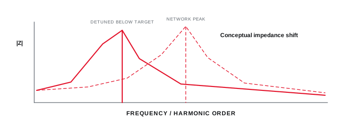
A conventional bank may remain appropriate where harmonic levels and resonance margin are acceptable. A detuned branch intentionally shifts the capacitor-reactor series resonance below a targeted harmonic region and changes component voltage and current duty. Active filtering addresses selected current harmonics through a converter and has different limits.
Define the final acceptance measurement at the PCC and at the capacitor bus, including capacitor current, reactor temperature where present, voltage distortion and the production states included.
Evidence basis[1] International Electrotechnical Commission[2] International Electrotechnical Commission[3] IEEE Standards Association
Choose conventional, detuned or active response from evidence
The solution follows the source, spectrum, reactive objective and expected operating states rather than one harmonic snapshot.

Final ratings, protection, earthing, settings and interlocks follow approved project engineering.
Open full-size SVGInformation that makes the next review more useful.
- 01
Provide the transformer rating, impedance and normal parallel or split operation.
- 02
Record available short-circuit information at the proposed capacitor connection point.
- 03
List existing and proposed capacitor stages, detuning reactors and fixed compensation.
- 04
Measure voltage and current harmonic spectra during representative operating states.
- 05
Identify drives, rectifiers, UPS systems, furnaces and other non-linear loads by feeder.
- 06
Review utility or generator source changes that materially alter system strength.
- 07
Escalate from screening to a fuller study when the resonance margin or data quality is uncertain.
Standards and technical references.
Links identify the source and scope; access to a complete standard may require purchase or organisational access.
- 01IEC 61642:1997 — Filters and shunt capacitors in harmonic-affected networksInternational Electrotechnical Commission
- 02IEC 60831-1:2014 — Low-voltage self-healing shunt power capacitorsInternational Electrotechnical Commission
- 03IEEE 519-2022 — Harmonic control in electric power systemsIEEE Standards Association
Questions engineers and project teams ask.
Do capacitor banks create harmonics?
Capacitors are not usually the harmonic source, but they change system impedance and can amplify existing harmonic voltage or current when resonance is near a present harmonic order.
Is an approximate resonance-order calculation enough to select a reactor?
No. It is a screening tool. Final reactor and capacitor duty require the actual network, harmonic spectrum, operating states, manufacturer data and approved engineering method.