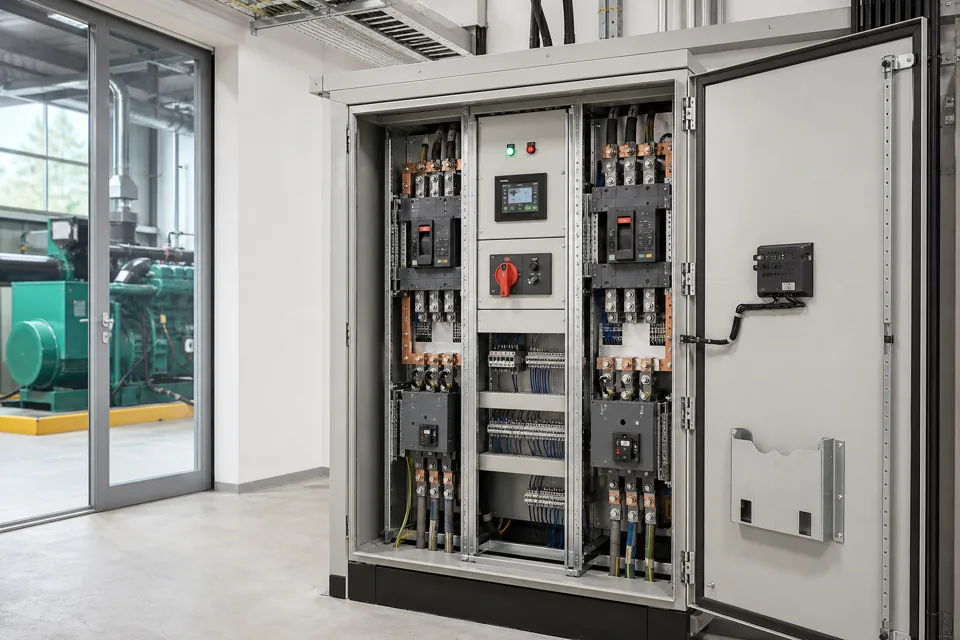
ATS commissioning proves more than movement between sources; it verifies sensing, interlocks, timing, load behaviour, fallback and the exact operating sequence.
- The approved operating sequence is the test basis for an automatic transfer system.
- Interlocking and source suitability must be proven before live transfer scenarios.
- Untested failure modes should be named explicitly rather than implied by a general pass statement.
Freeze the transfer and neutral philosophy
Sources, switching poles, earthing and permitted transitions establish the safe test boundary.
Confirm whether the system uses open, delayed or another approved transition; whether the neutral is switched; and how each source relates to the earthing arrangement. Record bypass or isolation functions where installed.
IEC 60947-6-1 applies to transfer switching equipment within its stated scope. The project sequence still needs source-specific settings, generator behaviour and site safety controls.
Evidence basis[1] International Electrotechnical Commission[2] International Electrotechnical Commission
Freeze the transfer and neutral philosophy
Sources, switching poles, earthing and permitted transitions establish the safe test boundary.
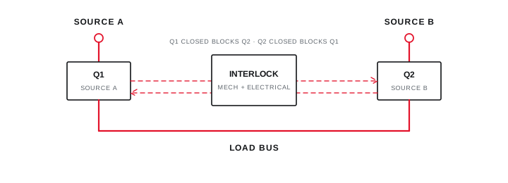
Final ratings, protection, earthing, settings and interlocks follow approved project engineering.
Open full-size SVGProve sensing, interlocks and timing before load transfer
Controlled simulation verifies that the logic recognises source states and cannot command an unsafe device combination.
Check phase and source sensing, availability thresholds, delays, device feedback and interlock truth states. Simulate conditions through the approved method rather than disturbing a live supply without a controlled test plan.
Compare observed timing with the accepted cause-and-effect schedule and record both the command and actual device feedback.
Evidence basis[1] International Electrotechnical Commission[2] International Electrotechnical Commission
Prove sensing, interlocks and timing before load transfer
Controlled simulation verifies that the logic recognises source states and cannot command an unsafe device combination.
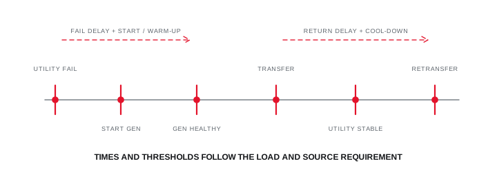
Final ratings, protection, earthing, settings and interlocks follow approved project engineering.
Open full-size SVGWitness the complete sequence and fallback
The final test includes load response, unsuccessful actions, restoration and operator recovery.
Where authorised, observe source loss, alternate-source availability, transfer, restoration and retransfer with representative load. Confirm that essential control power and indications remain intelligible through the transition.
Test or document the response to a source that fails to become available, a switch that does not reach position and a manual-mode handover. Retain untested scenarios and the reason they were excluded.
Evidence basis[1] International Electrotechnical Commission[2] International Electrotechnical Commission[3] International Electrotechnical Commission
Witness the complete sequence and fallback
The final test includes load response, unsuccessful actions, restoration and operator recovery.
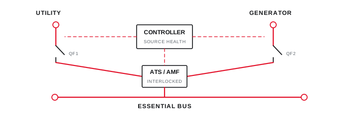
Final ratings, protection, earthing, settings and interlocks follow approved project engineering.
Open full-size SVGInformation that makes the next review more useful.
- 01
Approve the source, load, earthing, neutral and transfer philosophy before functional testing.
- 02
Verify mechanical and electrical interlocks, device identity and manual operating provisions.
- 03
Record voltage, frequency, phase and timing thresholds for each available source.
- 04
Test source failure, restoration and unsuccessful-transfer cases using an authorised simulation method.
- 05
Observe generator start, availability, load acceptance and retransfer sequence where included.
- 06
Confirm alarms, remote indications, emergency controls and manual fallback.
- 07
Retain witnessed results, time traces, settings and untested scenarios at handover.
Standards and technical references.
Links identify the source and scope; access to a complete standard may require purchase or organisational access.
- 01IEC 60947-6-1:2026 — Transfer switching equipmentInternational Electrotechnical Commission
- 02IEC 61439-2:2020 — Power switchgear and controlgear assembliesInternational Electrotechnical Commission
- 03IEC 60364-6:2016 — Verification of low-voltage installationsInternational Electrotechnical Commission
Questions engineers and project teams ask.
Does ATS commissioning require a real utility outage?
Not necessarily. Source conditions can often be simulated through an approved test method. Any live interruption requires an authorised plan coordinated with affected operations and safety controls.
What evidence should be retained after transfer-switch testing?
Retain the approved sequence, source and threshold settings, device map, observed timing, alarms, load response, manual fallback, witnessed results and explicitly untested scenarios.