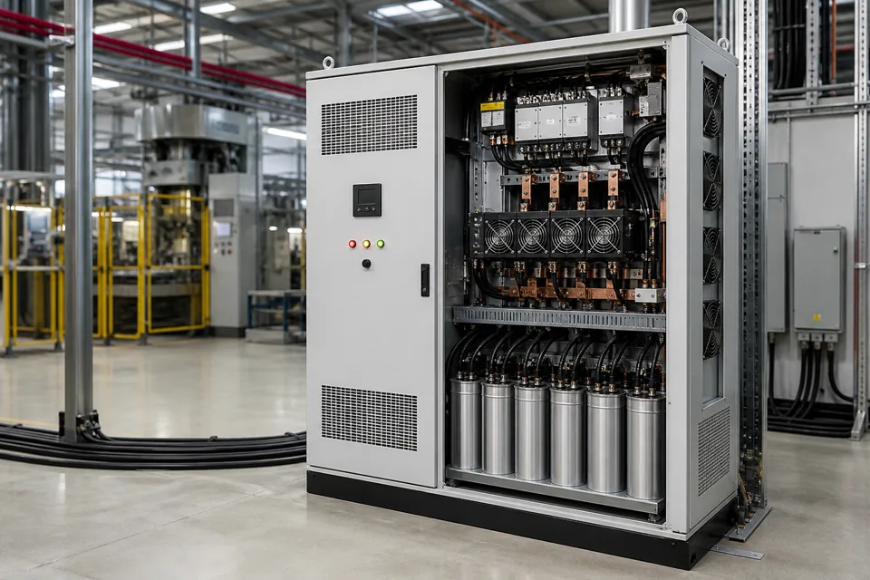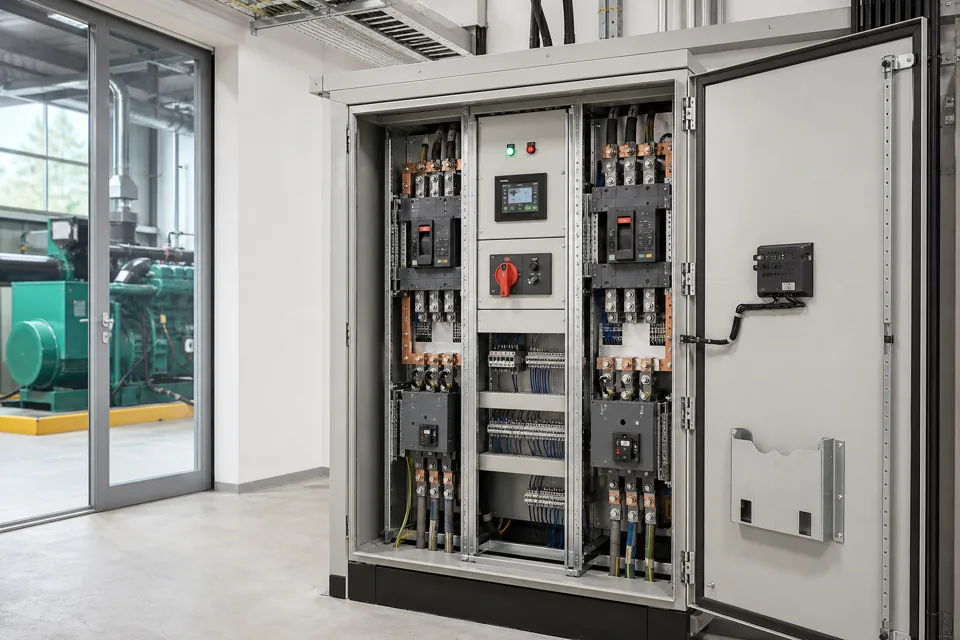
An automatic changeover system is a source-transfer function whose safe design depends on source compatibility, switching equipment, interlocks and the required load sequence.
- The transfer sequence must explicitly prevent unintended source paralleling unless a designed closed-transition system is specified.
- Neutral poles and earthing arrangements follow the installation and source topology, not a generic four-pole rule.
- Restoring all loads at once can overload a generator or cause unacceptable voltage and frequency excursions.
- Manual, remote and automatic modes need one coherent interlock and indication philosophy.
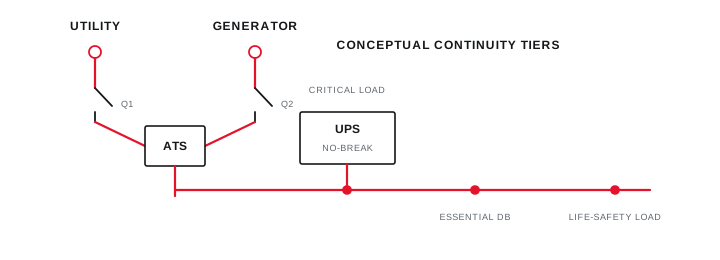
Map sources and essential loads
Document every source condition and the loads that must remain, return later or stay disconnected after transfer.
Record source voltage, frequency, phase sequence, short-circuit contribution, earthing arrangement and available capacity. For generators, include starting sequence, warm-up, cool-down and permissible step loading.
Group loads by continuity need and starting impact. Essential control and safety loads may transfer first, while large motors or non-essential process loads return through staged commands after the alternate source stabilises.
Map sources and essential loads
Document every source condition and the loads that must remain, return later or stay disconnected after transfer.
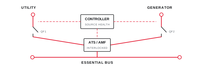
Final ratings, protection, earthing, settings and interlocks follow approved project engineering.
Open full-size SVGDefine the interlock and transfer sequence
Mechanical and electrical interlocks provide independent barriers against incompatible source connections.
An open-transition sequence confirms the active source device is open before closing the alternate source. The controller also supervises source health, device position and failure-to-operate conditions before advancing.
Manual operation, test modes and maintenance bypass can create different paths through the system. Each path must preserve the intended source relationship and make device position unambiguous.
Define the interlock and transfer sequence
Mechanical and electrical interlocks provide independent barriers against incompatible source connections.
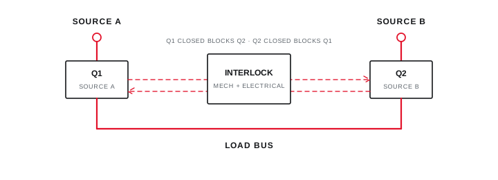
Final ratings, protection, earthing, settings and interlocks follow approved project engineering.
Open full-size SVGSet timing and load restoration deliberately
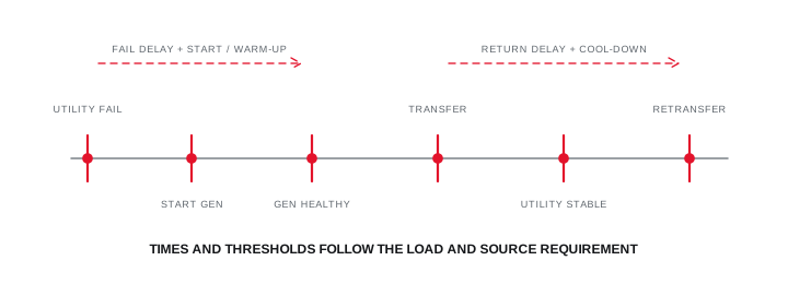
Detection, transfer and retransfer delays should distinguish a sustained source failure from a transient disturbance without delaying critical continuity unnecessarily.
Define undervoltage, phase-failure and frequency criteria against the connected equipment and source behaviour. A short delay can avoid nuisance generator starts for momentary disturbances, while the critical-load requirement limits acceptable interruption.
Retransfer to utility can include a stability delay and generator cool-down. Load sequencing should be tested with realistic starting currents and control dependencies rather than only no-load contact operation.
Set timing and load restoration deliberately
Detection, transfer and retransfer delays should distinguish a sustained source failure from a transient disturbance without delaying critical continuity unnecessarily.
Final ratings, protection, earthing, settings and interlocks follow approved project engineering.
Open full-size SVGSpecify transfer-equipment verification
Transfer switching equipment has device-level and assembly-level requirements that should be named in the project specification.
IEC 60947-6-1:2026 covers transfer switching equipment up to its stated voltage scope and includes automatic, remote, manual and specified bypass or closed-transition forms. The complete panel can also fall under relevant assembly requirements.
Acceptance should exercise source loss, unhealthy source, device failure, manual modes, alarms, retransfer and load sequence. Final tests follow safe approved procedures and do not improvise live-source simulations.
Specify transfer-equipment verification
Transfer switching equipment has device-level and assembly-level requirements that should be named in the project specification.
Final ratings, protection, earthing, settings and interlocks follow approved project engineering.
Open full-size SVGInformation that makes the next review more useful.
- 01
Utility, generator, UPS or alternate-source ratings and earthing arrangements.
- 02
Load current, motor starting, transformer inrush and priority groups.
- 03
Open, delayed, closed or bypass transfer requirement where applicable.
- 04
Neutral switching and source bonding information approved for the installation.
- 05
Source-health thresholds, delays, generator commands and retransfer sequence.
- 06
Mechanical and electrical interlocks plus manual operating requirement.
Standards and technical references.
Links identify the source and scope; access to a complete standard may require purchase or organisational access.
- 01IEC 60947-6-1:2026 — Transfer switching equipmentInternational Electrotechnical Commission
- 02IEC 61439-1:2020 — General rules for low-voltage assembliesInternational Electrotechnical Commission
- 03Central Electricity Authority safety and electric-supply regulations, 2023Central Electricity Authority, Government of India
Questions engineers and project teams ask.
Should every generator changeover panel switch the neutral?
Neutral switching depends on source earthing, bonding, protection and installation requirements. It must be resolved from the approved electrical architecture rather than assumed from a generic panel configuration.
What is the difference between ATS and AMF control?
Transfer switching changes the connected source, while an AMF function also supervises utility failure and commands generator start and stop. Project terminology varies, so the required sequence and boundaries should be written explicitly.