

An APFC panel is a controlled low-voltage capacitor-bank assembly whose useful design depends on the load profile, switching duty, harmonic environment and system boundary.
- APFC is a feedback-controlled bank, not merely a cabinet containing a fixed kVAr total.
- Step ratio and switching time should follow actual reactive-demand variation and acceptable hunting behaviour.
- Harmonic conditions can require detuning, filtering or a different compensation technology.
- Final ratings, protection and thermal design belong to the verified assembly and project data.
How an APFC panel works
A controller estimates the reactive requirement and commands protected capacitor stages to move the measured power factor toward its target.
The controller receives current information from a correctly oriented CT and a voltage reference from the monitored system. From their phase relationship it determines the direction and magnitude of reactive demand, then selects one or more available stages.
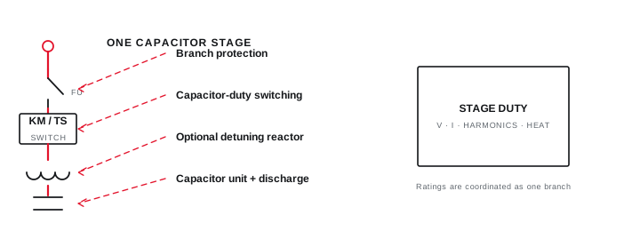
Each stage normally includes branch protection, a switching device and capacitors; detuned designs add a series reactor. Discharge arrangements and controller blocking times prevent unsafe or damaging re-energisation while residual capacitor voltage remains.
How an APFC panel works
A controller estimates the reactive requirement and commands protected capacitor stages to move the measured power factor toward its target.

Final ratings, protection, earthing, settings and interlocks follow approved project engineering.
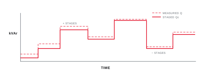
Open full-size SVGStep size, sequence and switching duty
Stage design trades response resolution, number of operations, thermal duty and the risk of oscillating around the target.
A coarse bank can leave a persistent error or over-correct at light load. Very fine stages provide resolution but add devices, switching operations and controller decisions. The useful sequence follows the measured rate and range of reactive-power change.
Conventional capacitor contactors suit loads that change slowly enough for mechanical switching and discharge delays. Rapidly varying loads can require thyristor-switched stages or continuously controlled equipment after the actual response requirement is established.
| Approach | Response | Useful when | Review carefully |
|---|---|---|---|
| Contactor APFC | Discrete, mechanical | Demand changes over seconds or minutes | Operations, inrush and discharge time |
| Thyristor APFC | Fast, discrete | Cyclic or rapidly changing demand | Thermal design and zero-cross control |
| SVG | Fast, continuous | Fine bidirectional reactive control | Converter rating and harmonic function |
| Fixed correction | No automatic response | Stable dedicated load | Over-correction when load is off |
Step size, sequence and switching duty
Stage design trades response resolution, number of operations, thermal duty and the risk of oscillating around the target.
Final ratings, protection, earthing, settings and interlocks follow approved project engineering.
Open full-size SVGCapacitor branch construction and protection
A stage is an engineered branch with switching, protection, conductors, discharge and heat-management requirements.
Capacitor current is influenced by voltage, tolerance and harmonic content, so branch components are not selected from nominal kVAr alone. The assembly design also accounts for short-circuit conditions, temperature rise, clearances, ventilation and maintainability.
IEC 60831 addresses self-healing low-voltage capacitor units, while IEC 61921 addresses low-voltage power-factor correction banks and aligns applicable assembly requirements with the IEC 61439 series. Project specifications can add further requirements.
Coordinate branch protection with capacitor and switching-device duties.
Provide discharge and controller timing appropriate to the capacitor arrangement.
Verify ventilation and temperature under the expected harmonic and ambient conditions.
Capacitor branch construction and protection
A stage is an engineered branch with switching, protection, conductors, discharge and heat-management requirements.
Final ratings, protection, earthing, settings and interlocks follow approved project engineering.
Open full-size SVGKnow when conventional APFC is not enough
Correction technology should follow the measured problem rather than the familiar product name.
A conventional bank does not actively cancel harmonic current, regulate voltage events or provide uninterrupted supply. In a harmonic-affected network, capacitors can interact with system inductance and may require detuning or a dedicated filtering strategy.
The selection decision should state the required outcome: tariff power-factor improvement, released current capacity, rapid reactive compensation, harmonic mitigation, voltage support or a combination. Each outcome has a different evidence and verification path.
Know when conventional APFC is not enough
Correction technology should follow the measured problem rather than the familiar product name.

Final ratings, protection, earthing, settings and interlocks follow approved project engineering.
Open full-size SVGInformation that makes the next review more useful.
- 01
Representative kW, kVAr and power-factor profile across normal operating states.
- 02
Transformer, voltage, source and point-of-connection information.
- 03
Major motors, drives, rectifiers, welders and cyclic loads.
- 04
Existing correction equipment, stage condition and controller settings.
- 05
Harmonic spectrum or a plan to measure it when non-linear loads are material.
- 06
Ambient, ventilation, cable, fault-level and installation constraints.
Standards and technical references.
Links identify the source and scope; access to a complete standard may require purchase or organisational access.
- 01IEC 60831-1:2014 — Low-voltage self-healing shunt power capacitorsInternational Electrotechnical Commission
- 02IEC 61921:2017 — Low-voltage power-factor correction banksInternational Electrotechnical Commission
- 03Technology compendium — Automatic power-factor controllerBureau of Energy Efficiency, Government of India
- 04Continuous Energy Improvement in Motor Driven Systems — power-factor correctionUnited States Department of Energy
Questions engineers and project teams ask.
Does an APFC panel always need detuning reactors?
No single answer applies to every network. Non-linear loads, measured harmonics, system impedance, existing capacitors and the intended correction point should be reviewed before choosing conventional, detuned or another approach.
Can an APFC panel correct voltage dips or interruptions?
A capacitor bank addresses reactive power and power factor. Voltage dips, interruptions and other power-quality phenomena require a separate causal assessment and may need different equipment or system changes.
Why does an APFC controller keep switching stages repeatedly?
Possible causes include a target too close to the operating variation, unsuitable step size, CT or voltage-reference errors, unstable loads, failed stages or controller settings that do not match the system.


