

APFC maintenance is strongest when inspection findings are compared with load, alarm, switching and previous-condition records instead of treated as isolated snapshots.
- Safe isolation and capacitor discharge are prerequisites to internal inspection.
- Switching counts and alarm history reveal duty that a visual snapshot cannot show.
- Trendable records are more useful than an undated pass-or-fail checklist.
Prepare the evidence before approaching the panel
Operating records shape the inspection plan and identify branches that deserve closer review.
Review recent power-factor trends, controller alarms, stage operation counts and any previous thermal or capacitance observations. A branch that rarely operates and a branch that cycles continuously present different questions even when both look clean after isolation.
Confirm the approved isolation and discharge process for the installed components. Residual voltage and stored energy must be addressed by competent persons using the project safety system and manufacturer information.
Evidence basis[1] International Electrotechnical Commission[2] International Electrotechnical Commission
Prepare the evidence before approaching the panel
Operating records shape the inspection plan and identify branches that deserve closer review.
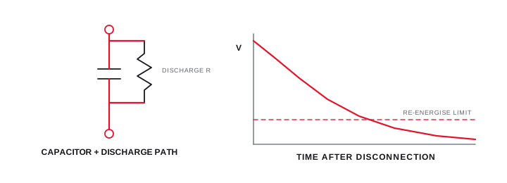
Final ratings, protection, earthing, settings and interlocks follow approved project engineering.
Open full-size SVGInspect the complete correction function
The review covers the enclosure, heat path, protection, switching and capacitor branch as one operating assembly.
Look for contamination, blocked ventilation, discolouration, loose mechanical supports, abnormal noise history, bulging or leakage, damaged discharge components and evidence of repeated switching stress. Where reactors are fitted, include their ventilation and thermal condition.
Do not infer electrical condition from appearance alone. Use approved measurements and component-specific criteria, and identify any finding that requires de-energised specialist testing or replacement evaluation.
Evidence basis[1] International Electrotechnical Commission[2] International Electrotechnical Commission[3] International Electrotechnical Commission
Inspect the complete correction function
The review covers the enclosure, heat path, protection, switching and capacitor branch as one operating assembly.
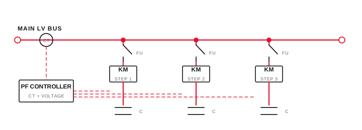
Final ratings, protection, earthing, settings and interlocks follow approved project engineering.
Open full-size SVGTurn observations into a trendable closeout
A maintenance report should preserve conditions, uncertainty and the action taken for every finding.
Record the system load, energised stage state, ambient condition and instrument used alongside measurements. Without those conditions, a later reader cannot distinguish real deterioration from a different operating point.
Classify each finding by evidence and consequence, assign an owner, and record whether the panel returned to service. A statement such as satisfactory should never hide an inaccessible compartment or an operating state that was not witnessed.
Evidence basis[2] International Electrotechnical Commission[3] International Electrotechnical Commission
Information that makes the next review more useful.
- 01
Define the isolation, discharge, verification and access method before opening the assembly.
- 02
Collect controller alarms, switching counts, power-factor trends and previous inspection records.
- 03
Inspect enclosure condition, ventilation path, contamination and evidence of abnormal heat or arcing.
- 04
Check each capacitor branch, switching device, reactor where fitted and protective component against records.
- 05
Record fastener or termination checks only where the approved maintenance method permits them.
- 06
Compare observed current and temperature patterns under a defined operating state.
- 07
Close findings with responsibility, evidence, limitation and next-review date.
Standards and technical references.
Links identify the source and scope; access to a complete standard may require purchase or organisational access.
- 01IEC 60831-1:2014 — Low-voltage self-healing shunt power capacitorsInternational Electrotechnical Commission
- 02IEC 61921:2017 — Low-voltage power-factor correction banksInternational Electrotechnical Commission
- 03IEC 60364-6:2016 — Verification of low-voltage installationsInternational Electrotechnical Commission
Questions engineers and project teams ask.
How often should an APFC panel be inspected?
The interval should come from operating duty, environment, manufacturer information, site maintenance policy and condition history rather than a universal calendar value.
Can visual inspection prove that a capacitor stage is healthy?
No. Appearance can reveal important defects, but electrical condition and switching performance require appropriate measurements, operating context and component-specific acceptance criteria.



