

An APFC controller needs a current signal that represents the source-side result of both the load and capacitor bank, with polarity and voltage phase reference confirmed before automatic switching.
- The CT must measure the electrical boundary that the capacitor bank is intended to correct.
- Polarity and voltage-phase pairing are functional inputs, not cosmetic wiring details.
- Commissioning should prove the sign and approximate magnitude of one controlled step before automatic mode.
Place the CT around the correction boundary
The controller should observe the upstream current after load and capacitor currents combine, so a switched step produces a visible source-side change.
In a typical central APFC arrangement, the incomer CT is upstream of the load bus and the capacitor-bank connection. That topology lets the controller compare the source current before and after a step is connected. A CT placed only around a selected load feeder, or on a path that excludes the capacitor current, can make the controller respond to an incomplete system picture.
The exact arrangement can differ for split buses, generators, multiple transformers, bus couplers or local compensation. Mark the intended correction boundary on the single-line diagram and check every normal operating state rather than copying a generic CT location.
Evidence basis[1] International Electrotechnical Commission[2] Schneider Electric
Show alternate-source, bus-coupler and generator operating states on the same measurement-boundary review.
Keep the CT secondary circuit safely shorted or connected according to the approved procedure; never leave an energised current-transformer secondary open.
Place the CT around the correction boundary
The controller should observe the upstream current after load and capacitor currents combine, so a switched step produces a visible source-side change.

Final ratings, protection, earthing, settings and interlocks follow approved project engineering.
Open full-size SVGConfirm polarity and voltage phase reference together
Current direction and voltage reference determine the controller's calculated reactive-power direction and displacement relationship.
CT primary polarity, S1/S2 secondary orientation and the selected voltage reference act as one measurement system. Reversing the current signal or pairing it with an unintended voltage phase can shift the calculated quadrant, produce an implausible power factor or prevent controller auto-initialisation.
Use the controller manual for the supported phase-connection combinations and never assume terminal naming is identical between devices. Record the installed combination in the panel drawing and settings schedule.
Evidence basis[2] Schneider Electric[3] ABB[4] International Electrotechnical Commission
Confirm polarity and voltage phase reference together
Current direction and voltage reference determine the controller's calculated reactive-power direction and displacement relationship.
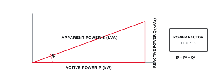
Final ratings, protection, earthing, settings and interlocks follow approved project engineering.
Open full-size SVGProve one step before releasing automatic control
A controlled manual test creates a traceable link between the physical capacitor stage, controller indication and measured system response.
With an approved stable operating condition, record baseline current, kW, kVAr and power factor. Command one known stage, confirm the expected contactor or thyristor indication, and check that reactive power moves in the intended direction without an abnormal current, voltage or alarm response.
The measured change will not equal the nameplate kVAr in every condition because voltage, tolerance, temperature and network behaviour matter. Treat the test as directional and diagnostic unless the test method and acceptance tolerance have been defined for the project.
Evidence basis[1] International Electrotechnical Commission[2] Schneider Electric
Prove one step before releasing automatic control
A controlled manual test creates a traceable link between the physical capacitor stage, controller indication and measured system response.
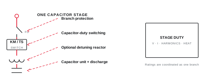
Final ratings, protection, earthing, settings and interlocks follow approved project engineering.
Open full-size SVGInformation that makes the next review more useful.
- 01
Share the latest single-line diagram showing the incomer, load bus, capacitor-bank connection and proposed CT location.
- 02
Record the CT ratio, class, secondary rating, burden, terminal markings and the controller current-input rating.
- 03
Identify which voltage phase or phase pair supplies the controller measurement reference.
- 04
Confirm conductor direction, CT primary polarity and secondary terminal continuity before energisation.
- 05
Record load kW, kVAr and power factor with all capacitor steps isolated.
- 06
Switch one verified step manually and record the direction and magnitude of the measured reactive-power change.
- 07
Retain the as-built wiring diagram, settings export and commissioning observations.
Standards and technical references.
Links identify the source and scope; access to a complete standard may require purchase or organisational access.
- 01IEC 61921:2017 — Low-voltage power-factor correction banksInternational Electrotechnical Commission
- 02PowerLogic VL power-factor correction controller user manualSchneider Electric
- 03RVT power-factor controller instruction manualABB
- 04IEC 60831-1:2014 — Low-voltage self-healing shunt power capacitorsInternational Electrotechnical Commission
Questions engineers and project teams ask.
Can the APFC controller CT be installed on any outgoing feeder?
Not for a central bank by default. The CT must represent the electrical boundary being corrected and must let the controller observe capacitor-step response. Split buses or local compensation need a topology-specific review.
What is the safest first commissioning check after CT wiring?
Under an approved stable condition, verify baseline sign and phase relationship, switch one known stage manually, and confirm that measured reactive power changes in the intended direction before enabling automatic control.



