

A reliable APFC commissioning record connects the installed CT and voltage reference to controller settings, physical capacitor stages and measured source-side response.
- Controller settings must reflect the installed CT, stage sequence and switching technology.
- A one-stage response test exposes polarity, mapping and measurement-boundary errors early.
- Automatic mode should be released only after alarms, off-time and safe fallback behaviour are recorded.
Freeze the measurement and control inputs
Record the system facts that determine how the controller calculates and acts before changing settings.
Start with the as-built CT ratio, polarity, source-side location and voltage phase reference. Then map the controller outputs to the physical stage schedule. A controller can display plausible numbers while acting on the wrong phase or switching a different stage than the one shown on screen.
Use the device manual for supported connection arrangements and parameter meanings. Do not copy target, C/K or delay values from another panel without reconciling them to the installed capacitor sizes, switching device and operating objective.
Evidence basis[1] International Electrotechnical Commission[2] Schneider Electric[3] ABB
Freeze the measurement and control inputs
Record the system facts that determine how the controller calculates and acts before changing settings.

Final ratings, protection, earthing, settings and interlocks follow approved project engineering.
Open full-size SVGProve the physical stage map one output at a time
A controlled manual sequence links software indication, output wiring and actual capacitor branch response.
With the required safety controls in place, operate each permitted output in manual mode and verify the intended branch indication. Confirm that stages are not duplicated, skipped or arranged against the approved sequence.
For one known stage under a stable load, compare baseline and post-switch kVAr, current and power factor. The test is directional unless the project defines measurement uncertainty and acceptance tolerances.
Evidence basis[1] International Electrotechnical Commission[2] Schneider Electric[3] ABB
Prove the physical stage map one output at a time
A controlled manual sequence links software indication, output wiring and actual capacitor branch response.
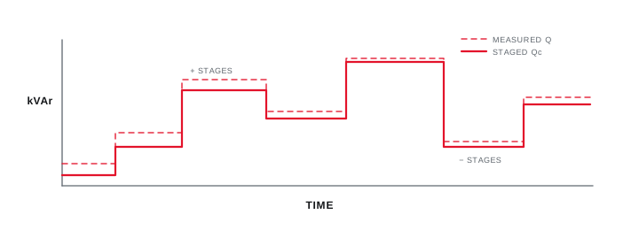
Final ratings, protection, earthing, settings and interlocks follow approved project engineering.
Open full-size SVGRelease automatic control with a retained record
Observe real decisions, alarms and re-switch timing before handing the controller to normal operation.
Watch the controller through representative load changes and confirm that the minimum off-time prevents an immediate unsafe reclose. Check over-voltage, under-current and temperature-related behaviours only through approved methods and manufacturer instructions.
Save the final parameter export, time-stamped measurements and open issues. The record should identify which operating states were witnessed and which remain outside the commissioning evidence.
Evidence basis[1] International Electrotechnical Commission[2] Schneider Electric[3] ABB
| Record | Purpose | Result |
|---|---|---|
| CT and phase reference | Establish measurement direction | Confirmed or corrected |
| Stage output map | Link command to branch | Matched to drawing |
| One-stage response | Prove source-side effect | Directional response recorded |
| Settings export | Create repeatable baseline | Version retained |
Information that makes the next review more useful.
- 01
Confirm the approved single-line, CT ratio and polarity, voltage reference and controller wiring schedule.
- 02
Record target power factor, switching programme, stage sizes, minimum off-time and alarm thresholds.
- 03
Match every output indication to the physical contactor or thyristor branch before automatic mode.
- 04
Measure baseline kW, kVAr, current and power factor with all stages isolated.
- 05
Command one known stage and verify the direction and approximate magnitude of source-side change.
- 06
Observe several automatic decisions under a representative and authorised load condition.
- 07
Export settings and retain the final test sheet with unresolved limitations clearly marked.
Standards and technical references.
Links identify the source and scope; access to a complete standard may require purchase or organisational access.
Questions engineers and project teams ask.
Which APFC controller settings should be recorded at handover?
Record the CT ratio and phase relationship, target power factor, switching programme, stage map, minimum off-time, alarm thresholds and a dated settings export tied to the as-built drawing.
Is a correct power-factor display enough to release automatic mode?
No. The physical stage map, one-stage reactive response, switching delay and alarm behaviour also need controlled verification under an authorised operating condition.



