
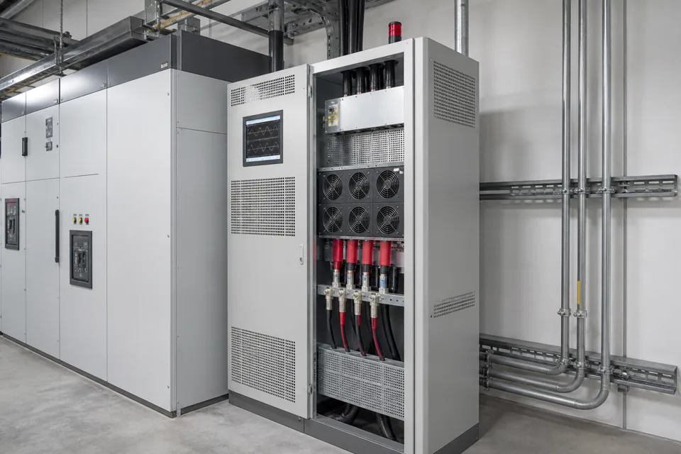
An active harmonic filter and a static VAR generator can share converter technology, but their primary control objectives and required ratings are not interchangeable.
- AHF rating follows the harmonic current to be compensated and the selected harmonic-control objective.
- SVG rating follows the reactive-current range and response required at the connection point.
- A combined function is possible only within the converter current and control capabilities specified and verified.
- Neither device replaces root-cause work on wiring, resonance, protection or unsuitable equipment operation.
Separate harmonic and reactive objectives
Harmonic distortion and fundamental-frequency reactive demand are different current components even when one converter can address both.
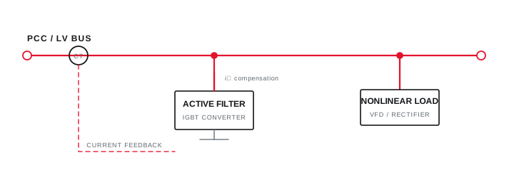
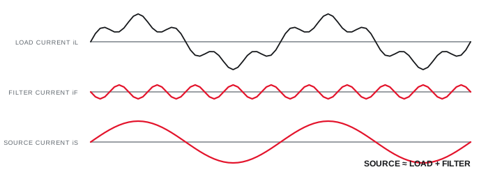
An active harmonic filter measures load or source current, extracts selected harmonic components and injects an opposing current through a shunt connection. Its purpose is to reduce harmonic current seen upstream within its bandwidth and rating.
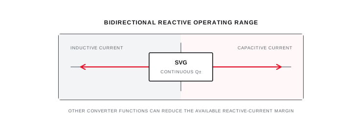
An SVG controls fundamental-frequency reactive current continuously and can operate in capacitive or inductive regions within its capability. Its purpose is rapid power-factor or voltage-support response, not automatically broad harmonic cancellation.
Separate harmonic and reactive objectives
Harmonic distortion and fundamental-frequency reactive demand are different current components even when one converter can address both.

Final ratings, protection, earthing, settings and interlocks follow approved project engineering.
Open full-size SVGActive harmonic filter compensation path
CT location, reference direction and the selected compensation objective define what current the filter attempts to cancel.
Place measurement CTs and the filter connection so the controller observes the targeted load current and injects compensation at the intended bus. Multiple transformers, generators, bus ties and existing filters can change the valid arrangement.
Verification compares the agreed current-distortion metric and spectrum before and after compensation at the specified operating states and boundary. A lower number at one light-load instant is not a complete acceptance result.
Active harmonic filter compensation path
CT location, reference direction and the selected compensation objective define what current the filter attempts to cancel.
Final ratings, protection, earthing, settings and interlocks follow approved project engineering.
Open full-size SVGStatic VAR generator operating region
The SVG adjusts converter current continuously across capacitive and inductive quadrants while observing its thermal and current limits.
Fast continuous response can suit rapidly varying reactive loads or fine correction around a target where discrete stages are too coarse. The required kVAr rating should cover the measured range with stated margin and the intended source configurations.
If a combined AHF and SVG function is offered, specify how converter current is prioritised when harmonic and reactive demands occur together. Total semiconductor current and cooling capacity remain finite.
Static VAR generator operating region
The SVG adjusts converter current continuously across capacitive and inductive quadrants while observing its thermal and current limits.
Final ratings, protection, earthing, settings and interlocks follow approved project engineering.
Open full-size SVGChoose against the measured requirement
Use a decision table to keep product selection aligned with the phenomenon, boundary and proof required.
A capacitor bank remains efficient for slowly varying lagging reactive demand when harmonics and switching conditions permit. Thyristor stages address faster discrete correction, SVG provides fast continuous reactive current, and AHF targets harmonic current.
Hybrid architectures can be appropriate, but added devices do not compensate for uncertain CT placement, incomplete system data or an undefined acceptance criterion.
| Technology | Primary function | Control form | Key sizing input |
|---|---|---|---|
| Contactor APFC | Lagging reactive correction | Discrete, slower | kVAr profile and stage range |
| Thyristor APFC | Rapid lagging correction | Discrete, fast | Cycle time and kVAr steps |
| SVG | Bidirectional reactive current | Continuous, fast | kVAr range and response |
| AHF | Harmonic-current compensation | Continuous waveform | Harmonic spectrum and amps |
Choose against the measured requirement
Use a decision table to keep product selection aligned with the phenomenon, boundary and proof required.
Final ratings, protection, earthing, settings and interlocks follow approved project engineering.
Open full-size SVGInformation that makes the next review more useful.
- 01
Harmonic current spectrum and demand at the intended point of connection.
- 02
Reactive-current range, sign and rate of change across operating states.
- 03
Voltage distortion, unbalance and event data where relevant.
- 04
Source, transformer, generator and capacitor-bank operating combinations.
- 05
Required response, redundancy, expansion and verification criteria.
- 06
Ambient, enclosure, cooling and communications requirements.
Standards and technical references.
Links identify the source and scope; access to a complete standard may require purchase or organisational access.
Questions engineers and project teams ask.
Can one converter provide both harmonic and reactive compensation?
Some equipment supports combined functions, but the specification must define current allocation, priorities, operating range and verification because both functions use the converter's finite current and thermal capacity.
Is an AHF sized from transformer kVA?
Transformer information is part of the system context, but AHF sizing primarily follows the harmonic current spectrum, operating demand, target boundary, required attenuation and installation conditions.


