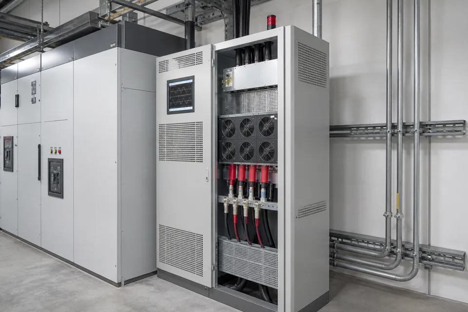
AHF commissioning connects the installed sensing and converter configuration to a measured before-and-after result at the agreed harmonic boundary.
- CT boundary and polarity determine whether the filter sees and opposes the intended current.
- Before-and-after measurements require the same boundary and a comparable operating state.
- Residual distortion can reflect converter headroom, unaddressed loads or source-voltage conditions.
Prove the sensing and compensation boundary
CT placement, polarity and phase mapping must agree with the configured source-load topology.
Trace each CT from conductor orientation through terminals to the filter input. Confirm whether the filter compensates a feeder, bus section or complete source and how parallel sources or tie states change that boundary.
Record the target harmonic orders or operating mode supported by the selected equipment. Do not infer device capability from the generic category name.
Evidence basis[1] International Electrotechnical Commission[2] International Electrotechnical Commission
Prove the sensing and compensation boundary
CT placement, polarity and phase mapping must agree with the configured source-load topology.
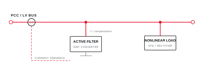
Final ratings, protection, earthing, settings and interlocks follow approved project engineering.
Open full-size SVGCapture a comparable baseline and staged enablement
A stable operating-state record makes the direction and magnitude of compensation interpretable.
With the filter safely disabled, record voltage and current spectrum, RMS current, load and active operating state at the agreed boundary. Then enable a limited compensation command and confirm current reduces in the expected direction without abnormal alarms.
Increase to the approved setting while observing converter loading, thermal state and residual spectrum. Stop on unexpected amplification, phase error or protection operation and resolve the sensing chain first.
Evidence basis[1] International Electrotechnical Commission[2] International Electrotechnical Commission[3] IEEE Standards Association
Capture a comparable baseline and staged enablement
A stable operating-state record makes the direction and magnitude of compensation interpretable.
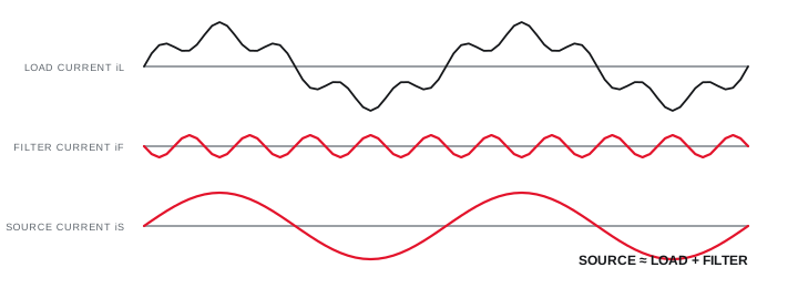
Final ratings, protection, earthing, settings and interlocks follow approved project engineering.
Open full-size SVGVerify residual performance and converter headroom
Final evidence should show the result, active constraints and states that were not witnessed.
Repeat the baseline measurement method after the system settles and compare individual orders as well as the selected aggregate metric. Record whether the filter reaches its current or thermal limit during the observed state.
IEC 62477-1 provides group safety requirements for power-electronic converter systems within its scope. Product instructions remain authoritative for installation, service, protection and commissioning of the selected filter.
Evidence basis[1] International Electrotechnical Commission[2] International Electrotechnical Commission[3] IEEE Standards Association
| Evidence | Confirms | Possible finding |
|---|---|---|
| CT phase check | Sensing identity | Reversed or crossed phase |
| Baseline spectrum | Initial load state | Wrong boundary |
| Staged enablement | Compensation direction | Amplification or alarm |
| Residual and loading | Available headroom | Current-limited operation |
Information that makes the next review more useful.
- 01
Confirm the approved single-line, harmonic objective and named measurement boundary.
- 02
Verify CT location, ratio, polarity, phase association and summation for parallel units.
- 03
Record supply voltage, fault level, cable, protection, ventilation and environmental conditions.
- 04
Capture a baseline voltage and current spectrum with the filter disabled under a stable load state.
- 05
Enable compensation in controlled stages and watch current direction, alarms and converter loading.
- 06
Repeat measurements at the same boundary and aggregation settings after the system settles.
- 07
Retain final parameters, trends, residual spectrum, limitations and safe bypass instructions.
Standards and technical references.
Links identify the source and scope; access to a complete standard may require purchase or organisational access.
- 01IEC 62477-1:2022 — Safety requirements for power electronic converter systemsInternational Electrotechnical Commission
- 02IEC 61000-4-30:2025 — Power-quality measurement methodsInternational Electrotechnical Commission
- 03IEEE 519-2022 — Harmonic control in electric power systemsIEEE Standards Association
Questions engineers and project teams ask.
Can an active harmonic filter be commissioned from its display alone?
No. Independent or suitably controlled measurements at the agreed boundary are needed to verify sensing, compensation direction and the before-and-after result.
Why might residual harmonic current remain after AHF commissioning?
The filter may be current limited, configured for selected orders, sensing only part of the load, operating in another priority mode or affected by source and load conditions.