
Power Quality
Static VAR Generators & Advanced SVG
Power-electronic equipment for rapid and continuously controlled reactive-power compensation within an assessed electrical system.
- Pathway
- Power quality
- Basis The final rating and component selection follow actual load, system and site inputs.
- Configured to application
- Reviewed This is the latest editorial and technical-content review date, not a product certification date.
- 08 Aug 2026

When this solution is considered
- Reactive-power demand changes too quickly or finely for a conventional stepped correction approach.
- The load profile includes light-load, leading or rapidly changing operating conditions that need dynamic control.
- A power-quality review identifies a requirement for electronic reactive-power compensation.
What we need to understand
The useful starting point is the actual electrical system and operating requirement—not a generic rating request.
- 01
Time-based reactive-power, power-factor and demand measurements across representative operations.
- 02
Single-line diagram, system voltage and proposed connection point.
- 03
Load inventory, switching patterns and known regenerative or leading-load behavior.
- 04
Existing APFC, harmonic-filter and capacitor equipment details.
- 05
Installation space, ventilation, environmental and communication requirements.
Static VAR Generators — engineering principle
This diagram explains the functional pathway only. Device ratings, protection settings, conductor sizing and interlocks are engineered from the approved project inputs.
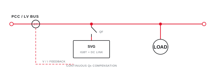
Final ratings, protection, earthing, settings and interlocks follow approved project engineering.
Open full-size SVGConfiguration considerations
- Dynamic compensation capacity follows the measured reactive-power range and operating transitions.
- Current sensing, connection point and coordination with existing correction equipment are engineering decisions.
- Protection, cooling, enclosure, monitoring and communication are defined in the project scope.
Typical applications
These examples indicate where the solution may be considered; they do not represent completed Arnav projects.
- Rapidly changing industrial loads where reactive-power demand varies within short operating cycles.
- Facilities with mixed load conditions that may move between lagging and leading behavior.
- Projects where measured data supports a continuously controlled compensation approach.
Frequently asked questions
How does an SVG differ from a conventional APFC panel?
An SVG uses power electronics for continuously controlled compensation, while a conventional APFC arrangement switches configured capacitor steps. Suitability depends on measured load behavior and project needs.
What data supports SVG capacity selection?
Representative time-based reactive-power and power-factor measurements, operating-state information, the single-line diagram and details of existing correction equipment support selection.
Can SVG and existing capacitor equipment operate together?
A coordinated arrangement may be possible, but sensing, control interaction, connection points, harmonic conditions and the role of each system must be engineered explicitly.
Need help?
Share your static var generators requirement.
Send the information already available. The initial review can identify the remaining inputs needed to define scope.
Measure before selecting the function
Observed symptoms lead to a defined measurement boundary, an evidence-led function and a verified outcome.

Final ratings, protection, earthing, settings and interlocks follow approved project engineering.
Open full-size SVG