
Power Conditioning
Isolation Transformers
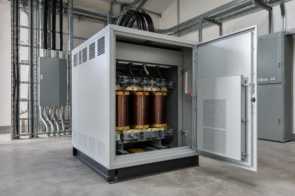
Transformer solutions used where an application requires electrical separation between the incoming and outgoing circuits.
- Pathway
- Power conditioning
- Basis The final rating and component selection follow actual load, system and site inputs.
- Configured to application
- Reviewed This is the latest editorial and technical-content review date, not a product certification date.
- 08 Aug 2026
When this solution is considered
- The application calls for galvanic separation between a source circuit and the connected equipment.
- A project specification identifies isolation, shielding or neutral arrangement as part of the electrical design.
- Sensitive or specialised equipment requires a dedicated transformer scope reviewed with the equipment supplier.
What we need to understand
The useful starting point is the actual electrical system and operating requirement—not a generic rating request.
- 01
Input and output voltage, frequency, phase arrangement and required capacity basis.
- 02
Load type, operating profile, starting behavior and known inrush characteristics.
- 03
Neutral, earthing, shielding and circuit-separation requirements.
- 04
Protection, temperature, ventilation, acoustic and enclosure requirements.
- 05
Installation location, cable access, space and environmental conditions.
Isolation Transformers — engineering principle
This diagram explains the functional pathway only. Device ratings, protection settings, conductor sizing and interlocks are engineered from the approved project inputs.
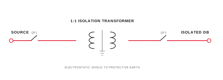
Final ratings, protection, earthing, settings and interlocks follow approved project engineering.
Open full-size SVGConfiguration considerations
- Winding, voltage and phase arrangement must follow the electrical system and connected-load requirements.
- Shielding, neutral and earthing details are project decisions rather than generic catalogue assumptions.
- Enclosure, ventilation, protection, monitoring and installation interfaces depend on the site context.
Typical applications
These examples indicate where the solution may be considered; they do not represent completed Arnav projects.
- Industrial control and instrumentation circuits that require a defined separation point.
- Dedicated equipment supplies where the project specification calls for isolation.
- Facility electrical systems requiring an application-specific transformer arrangement.
Frequently asked questions
What details are needed to size an isolation transformer?
Provide the load capacity basis, voltage and phase arrangement, frequency, load type, operating and starting behavior, earthing needs, environmental conditions and applicable project specification.
Does an isolation transformer correct every power-quality issue?
No. Isolation addresses circuit separation and certain disturbance paths, but voltage variation, harmonics, transients and other conditions require separate measurement and application review.
Can shielding and enclosure details be configured?
Yes, where the project requires them. Shielding, enclosure, ventilation, protection, monitoring and access details must be defined against the installation and specification.
Need help?
Share your isolation transformers requirement.
Send the information already available. The initial review can identify the remaining inputs needed to define scope.
Measure before selecting the function
Observed symptoms lead to a defined measurement boundary, an evidence-led function and a verified outcome.

Final ratings, protection, earthing, settings and interlocks follow approved project engineering.
Open full-size SVG