
Power Quality
APFC Panels
Arnav Industries & Electricals manufactures APFC panels for managing reactive-power demand as connected inductive loads change during operation.
- Pathway
- Power quality
- Basis The final rating and component selection follow actual load, system and site inputs.
- Configured to application
- Reviewed This is the latest editorial and technical-content review date, not a product certification date.
- 08 Aug 2026

When this solution is considered
- Measured power factor varies as motors, utilities or process loads cycle through different operating states.
- A project needs staged reactive-power correction rather than a fixed correction arrangement.
- The installation is being reviewed for power-factor performance and the suitability of its existing correction equipment.
What we need to understand
The useful starting point is the actual electrical system and operating requirement—not a generic rating request.
- 01
Connected load, demand profile and typical operating combinations.
- 02
System voltage, frequency, transformer details and single-line diagram.
- 03
Recent power-factor, demand and energy-billing information where available.
- 04
Harmonic measurements or known non-linear loads where available.
- 05
Existing capacitor-bank details, switching condition and available installation space.
- 06
Site temperature, ventilation, dust exposure and cable-entry conditions.
APFC Panels — engineering principle
This diagram explains the functional pathway only. Device ratings, protection settings, conductor sizing and interlocks are engineered from the approved project inputs.
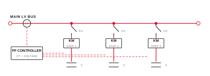
Final ratings, protection, earthing, settings and interlocks follow approved project engineering.
Open full-size SVGConfiguration considerations
- Reactive-power requirement and step arrangement depend on measured or reliably established load behavior.
- Contactor, detuned-reactor or faster switching approaches are selected only after reviewing application conditions.
- Protection, ventilation, controller inputs, enclosure and interfaces follow the agreed electrical design basis.
Typical applications
These examples indicate where the solution may be considered; they do not represent completed Arnav projects.
- Industrial facilities with motors, pumps, fans, compressors and varying utility loads.
- Production environments where load combinations change throughout a shift or process cycle.
- Existing facilities reviewing correction capacity, switching behavior or harmonic conditions.
Frequently asked questions
How is APFC panel capacity selected?
Selection should use the installation load profile, measured or calculated reactive-power requirement, transformer and system data, operating combinations and the target defined for the project.
When should harmonics be checked before selecting APFC equipment?
Harmonics should be considered whenever significant non-linear loads are present, existing capacitors show distress, measurements indicate distortion or the project information requires a detuned or dynamic approach.
Can an APFC proposal be prepared from an electricity bill alone?
A bill can support an initial discussion, but dependable configuration normally needs the single-line diagram, load profile, system parameters and relevant measurements or existing equipment details.
Need help?
Share your apfc panels requirement.
Send the information already available. The initial review can identify the remaining inputs needed to define scope.
Measure before selecting the function
Observed symptoms lead to a defined measurement boundary, an evidence-led function and a verified outcome.

Final ratings, protection, earthing, settings and interlocks follow approved project engineering.
Open full-size SVG