
Industry operating context
AIE / IND / 03Manufacturing Electrical Solutions
Control panels, power-quality solutions, wiring and project support for production machinery, plant utilities and facility upgrades.

Map changing loads, line or utility states and production constraints.
Keep source, machine, automation and retained-equipment boundaries visible.
Tie decisions to drawings, measurements, specifications and site facts.
Operating pressure map
What changes the electrical decision in this environment.
These are context prompts, not assumptions about a particular plant.
- 01
Facilities often combine legacy machines, new automation, utilities and distribution equipment with different documentation quality.
- 02
Load growth and changed operating patterns can expose capacity, power-factor, harmonic or voltage concerns.
- 03
Execution must balance production continuity, safe shutdowns, access and coordination across multiple work fronts.
Project information console
Bring the facts that make the first review useful.
- 01Input channel
Current single-line diagrams, load lists, machine information and the objective of the change.
- 02Input channel
Operating patterns, planned additions and any relevant power or energy measurements.
- 03Input channel
Site layout, cable routes, available space, shutdowns and retained-system interfaces.
- 04Input channel
Required drawings, checks, delivery milestones and installation responsibilities.
Relevant pathways
Products and services stay separate—then meet at the project boundary.
Open a catalogue page for the engineering inputs and configuration decisions specific to that solution family.


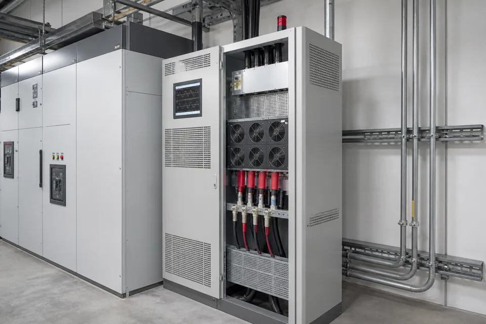
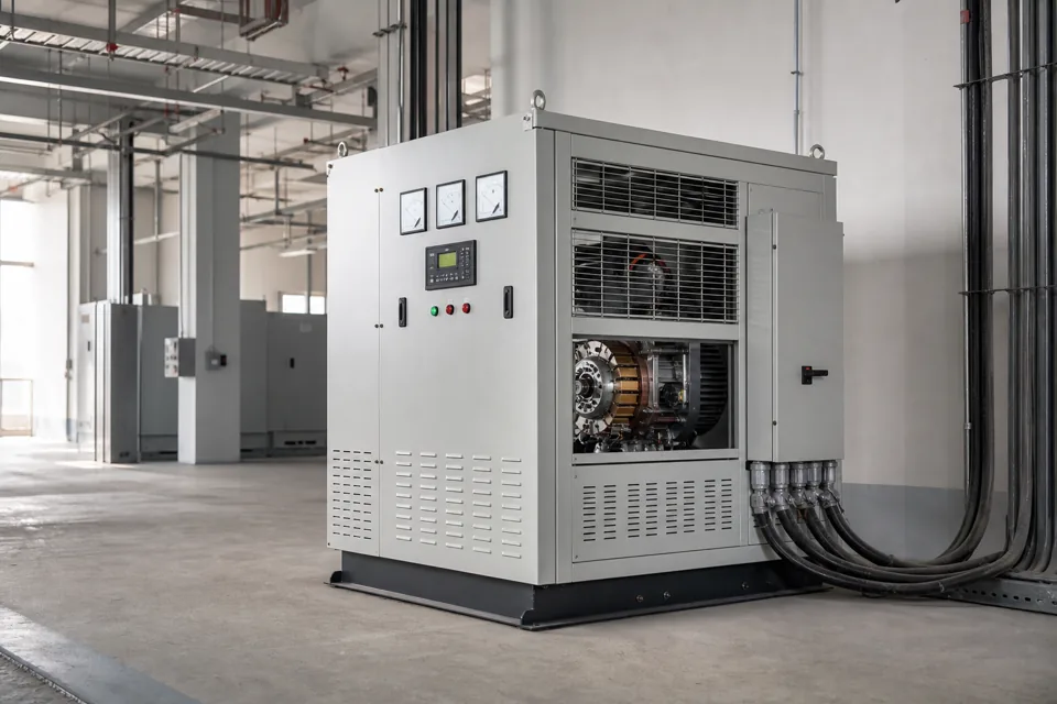
Industrial wiring work begins with drawings, cable schedules, interfaces, access and responsibility boundaries so the installation scope can be planned against actual site conditions.
03assessmentElectrical AuditsAn electrical audit is scoped around the questions the site needs answered, the systems available for review, measurement access and the form of findings required for decisions.
05project supportProject SupportProject support connects the technical requirement to an executable scope by coordinating available information, responsibilities, interfaces, decisions and agreed deliverables.
Engineering questions
Answers should follow the actual facility.
Can a project begin when existing drawings are incomplete?
Yes, but the initial scope should include verification and gap closure. Unknown circuits, retained equipment and site conditions must be recorded rather than assumed.
How should a future load addition be assessed?
Review the source and transformer, feeder capacity, protection, demand profile, starting behavior, power factor, harmonics, voltage conditions, space and the operating impact of the new load.
Need help?
Plan a manufacturing electrical requirement.
Share the operating states, system boundary, available drawings, measured conditions and constraints that shape the project.
Source, transfer and load boundary
A conceptual source-to-load context for discussion; ratings, protection and interlocks follow project engineering.

Final ratings, protection, earthing, settings and interlocks follow approved project engineering.
Open full-size SVG